Bob's No. 1

Home Model Engine Machinist Forum

Help Support Home Model Engine Machinist Forum:

This site may earn a commission from merchant affiliate links, including eBay, Amazon, and others.

BobWarfield

Well-Known Member
Joined
Dec 27, 2007
Messages
1,151
Reaction score
1
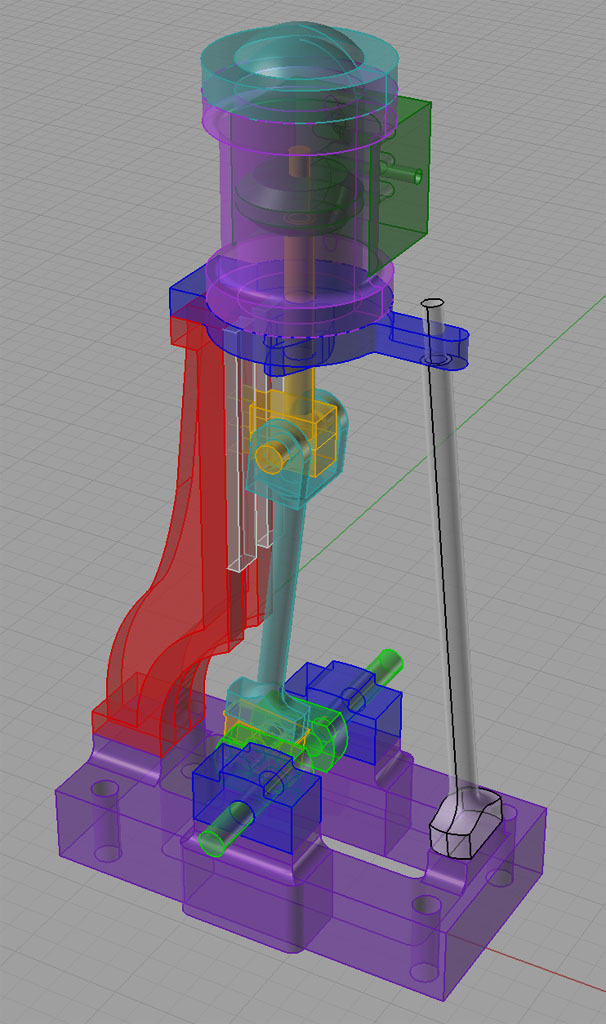
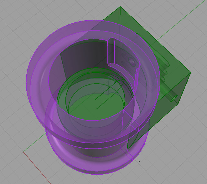
I was taking another gander at the magnificent photos on John Bentley's (The Engine Man) site when I decided to have a go at modeling a similar steam engine. Bentley's engine is loosely based on Stuart Turner's No. 1, so I thought i"d call this design exercise "Bob's No. 1" as well. It's amazing how much time you can spend on one of these and how neat they turn out. I got this far after about 2 hours:

ConRodError.jpg


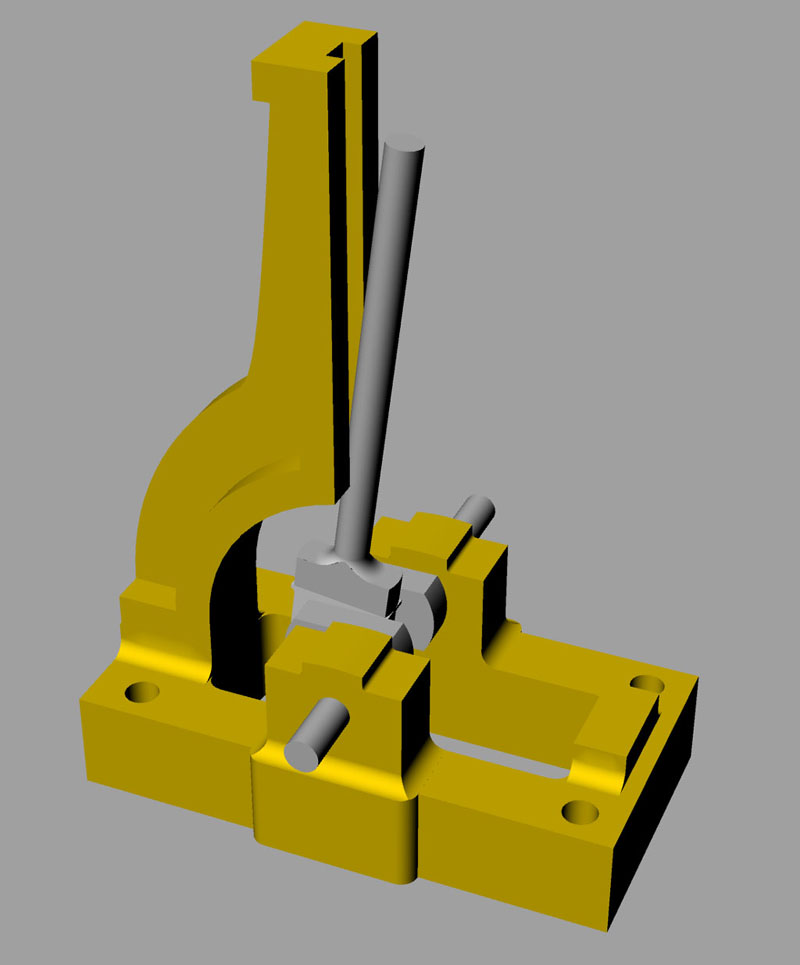
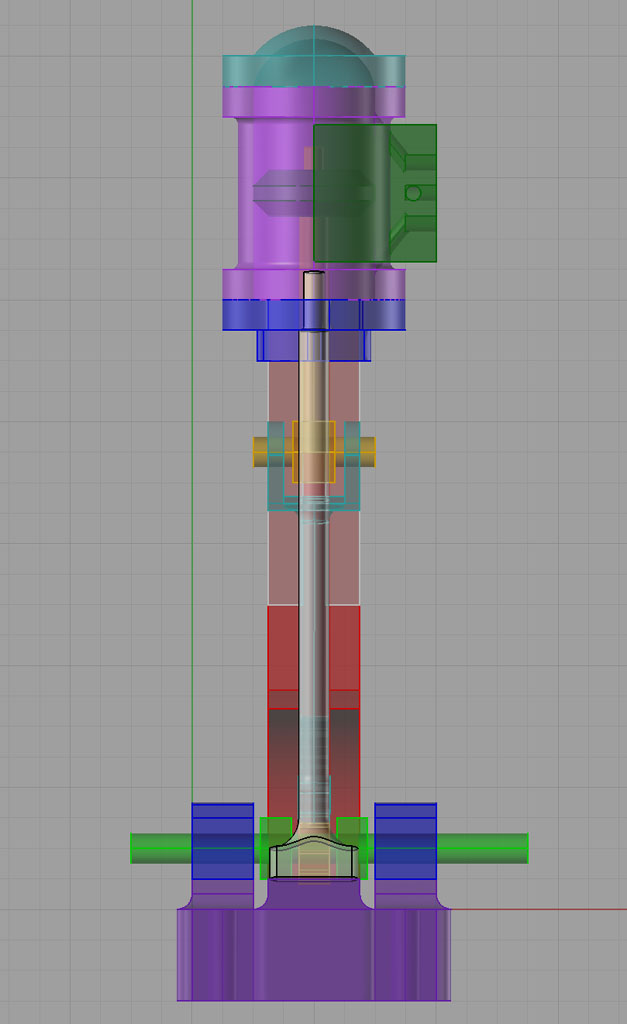
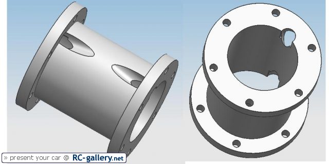
Here are some more views:

ConRodError2.jpg


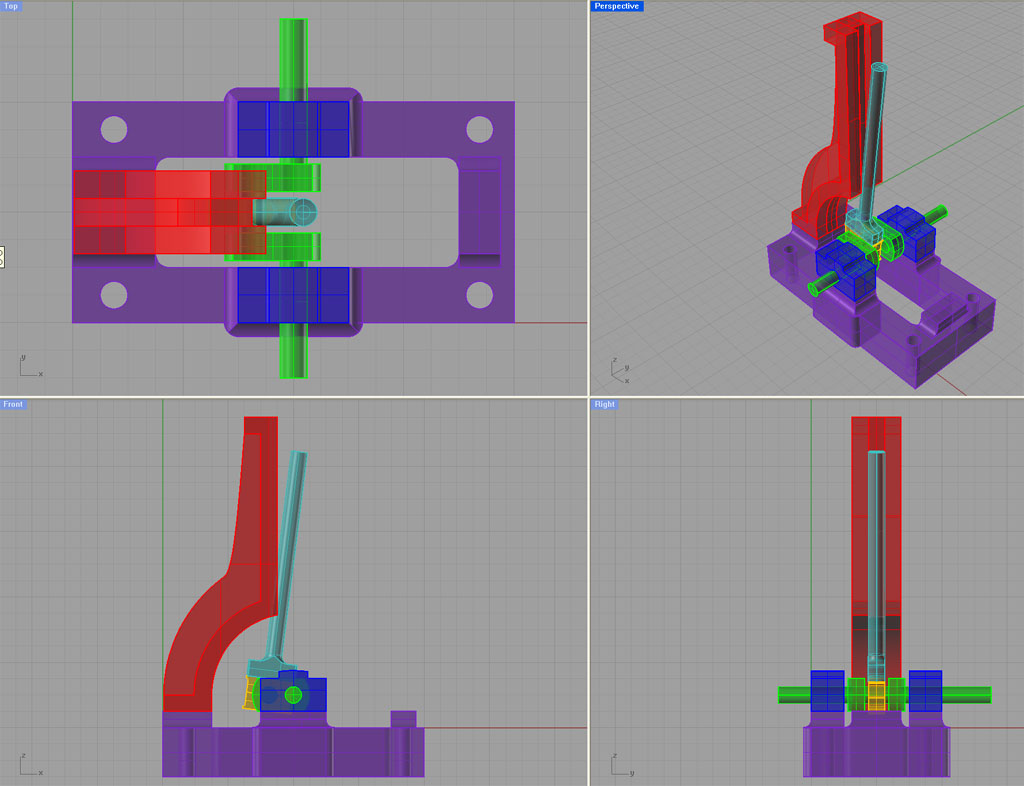
As you can see, I've got an interference problem with the con rod at present. I'll have to redesign the standard to clear it. Good thing I could see that in the CAD model, LOL!

This much took me about 2 hours. I'm not sure when I'll finish it. I was feeling kind of inspired and it had been a while since I fired up Rhino3D. I've got a lot else to deal with at the moment, but it was a fun couple of hours. I reckon I'm probably a good 12-16 hours of work from really finishing.

If I do get the drawings finished, they'll make a nice CNC project for me.

Hope you enjoyed!

Cheers,

BW
 
Spent a few more hours on this steam engine this evening and got quite a bit further:

PerspectiveJul13%20copy.jpg


RightJul13.jpg


It's been quite a good learning experience for me to sharpen my skills on the CAD program and learn a bit more about what makes one of these slide valve engines tick.

Next I have to finish off the steam chest with its eccentric linkage. I may have to research a reversing gear for it as well.

Cheers,

BW
 
Hi Bob

Why do you plan the piston in that shape? ???
This causes higher wear to the piston because its contact surface with the cylinder is smaller and in the end you will have to replace the piston earlier.

Florian
 
Thats exremely good looking drawing, lots better than I can do..Indeed eventually I hope to be able to quick make drawings of some of my ideas and therewith work through some of the variations on the theme.....If a man had the skills , how long would it take to make one of them drawings?..
 
Bob, tell me again what software you are using here?

Chuck
 
That'll be one neat looking engine there Bob. About how tall will it be?

And, Ya, what Florin said. Why the odd looking piston? ???

Bernd
 
Thank you for your kind attention.

Some answers:

- Why is the piston shaped so funny? There is a functional purpose to it. If you look closely you'll spot it. It isn't the only way to solve the problem, but it was an acceptible way to me and easier than the other ways I thought of. I may yet change it, but wanted to get on with drawing the rest of the engine. Besides, a thin piston then becomes an additional safety valve on the boiler. ;D As for wear, I doubt it'll see enough miles for that to be an issue.

- Time with skills? Unknown, as I don't really claim to have skills. This drawing took me about 6-7 hours. I had to redo several portions 2 or 3 times for it all to work out mechanically. For example, I repositioned the moving assembly to check clearances at top dead center, bottom dead center, and the "resting" positing nearest the standard that it's in. Several problems were discovered and design changes were instituted. I'm sure there will be even more of that with the steam chest and eccentric.

- As was mentioned, the program is indeed Rhino 3D. $788 from novedge.com. Be sure to shop, different outfits discount it differently. I think I got mine for $695. Whether that is a lot or a little depends on your perspective. All these CAD programs are kind of a bear to get any good at, so I wanted one I could live with for a long time. I also bought Alibre and used it for 3 months, but just didn't like it as well. Others strongly prefer it. I'd try several and see what fits, but just remember it'll take you 3-4 drawings to feel at all comfortable enough to make a judgement on which is best.

- Bernd, on size, this one is currently 4" x 2" x 8" tall or so. But the size is kind of immaterial, it's more about proportion. If I like the proportions, I can scale it very quickly in the CAD program to about any size I like. Keep in mind that can change the running characteristics, especially for touchy things like an LTD Stirling. Should be fine for a pretty wide range for this sort of engine though.

I find this program has been extremely useful in machine work for me. While CAD is indispensible for CNC, it's also darned handy for manual machining work. For example, when I was making up the Team Build I immediately redrew the parts with decimal dimensions instead of fractions and stuck the prints up in the shop with magnets. Perhaps more interesting is the ability to "calculate by drawing." For example, to figure the mechanical clearances on the steam engine above just by moving the parts as they would in the working prototype and taking dimensions you can "measure" what's happening without resorting to trigonometry. Or, when I was fitting my collet chuck to a backplate, I knew I had an error, but wanted to figure out exactly how to compensate for it. I describe how I used the CAD program to do that here:

http://www.cnccookbook.com/CCColletChuck2.htm

All in all, not sure I could be very productive without my CAD program. For those that are curious, a bunch more of my drawings are up on my web site here:

http://www.cnccookbook.com/MTCNCRhinoPen.htm

They give a little idea of what you can do with Rhino3D even if you're not all that skilled like me!

Cheers,

BW
 
Nice drawings!! :bow:

I am not trying to hijack your thread, but the questions about CAD and drawing programs lead me to ask if anyone uses Google's drawing program SketchUP?

I have used it to lay out some of my model stuff and it is quite amazing for the price: Free! ;D It is fun and relatively easy to use especially if you've not used a 3D drawing program. Try the download here:

http://sketchup.google.com/

An example:

vertengine2.jpg
 
BobWarfield said:
Thank you for your kind attention.

Some answers:

- Why is the piston shaped so funny? There is a functional purpose to it. If you look closely you'll spot it. It isn't the only way to solve the problem, but it was an acceptible way to me and easier than the other ways I thought of. I may yet change it, but wanted to get on with drawing the rest of the engine. Besides, a thin piston then becomes an additional safety valve on the boiler. ;D As for wear, I doubt it'll see enough miles for that to be an issue.

Looks like you won't have to cut an opening in the top and bottom heads for the steam to enter the cylinder?

As far as an additional saftey valve for the boiler I won't think so, but I could (and usally am) wrong. :D

- Bernd, on size, this one is currently 4" x 2" x 8" tall or so. But the size is kind of immaterial, it's more about proportion. If I like the proportions, I can scale it very quickly in the CAD program to about any size I like. Keep in mind that can change the running characteristics, especially for touchy things like an LTD Stirling. Should be fine for a pretty wide range for this sort of engine though.

That's a pretty good size. I like the idea of being able to scale it once complete.

Bernd
 
Nice engine so far Bob! I really like the design.

*highjack

Bob is being modest about Rhino3D. I tried to use it and just couldn't wrap my head around it. However, I started using Alibre and that works very well for me. Maybe we should start a different thread about 3D cad software instead of highjacking Bob's thread about his engine.

*/highjack ;D

Eric
 
Duh! forget to ask Bob the question I wanted to in my previous post...

Bob, are you going to CNC the base or cast it?

Eric
 
Hi

I have seen the purpose of this strange looking piston.

But i think there is a much better way of doing it:

Take a 4mm endmill and cut a groove to the end of the cylinder (The endmill parallel to the piston), then your Pison just needs two very small chamfers.
Like that:

347_bee10073d776cc6258dcefcc3f8c0dc6.jpg


(hope you can recognize what i mean)

otherwise.. just tell me and i will make a sketch.

By the way, to reduce the weight of the moved parts, you can make a circular U-groove on both sides of your piston (just like the real ones)

Cheers
Florian

 
Florian, you did see the purpose of the piston bevel, and I do like your idea better! I will amend the drawings...

Brass, I would like to do both. CNC and cast. CNC is a wonderful way to produce the casting molds and casting is tremendously more economical on expensive brass than turning great big blocks into chips. What remains to be seen is whether I'll have time to build a foundry furnace and learn to cast. Just so darned many things to learn, do, and build in this silly hobby. I do think CNC and casting are great bedfellows though.

You also illustrate my point when I tell everyone that which CAD program I like is not important: you need to go try several and see which one YOU like. They're all different, all idiosyncratic, and they all have their pros and cons. Most of all, they all take a lot of learning. I can't imagine being proficient in more than one. You'll be making a fair time investment, so you want to make sure you like it well and won't have to switch later.

While we're on the subject, look carefully at the file format support your preferred program offers. Will you be able to exchange files with others in the common formats? Autocad, IGES, and several others (can't remember right now) are real important. If you will ever care about CNC you want to make sure you can share files with the CAM software out there to generate your g-codes.

Honestly, the CAD/CAM/CNC world is too hard right now. Too much too learn. Manual machining is a lot to learn for starters, and then to have all this computer stuff on top of it is hard. Then you have to throw all the electrical/electronics/motion control on top of that. I do computers for a living, so I actually like the silly buggers and tolerate it. Go figure.

Cheers,

BW
 
Here is a slight refinement on Florian's suggestion:

Change16.jpg


Since it'll be CNC, it's just as easy to cut a pocket with the 1/8" end mill as do a straight plunge groove. Hence I did a "Hot Rod Porting Job" on the cylinder.

For those curious about Rhino3D, I captured what it took for me to do this little redesign on a page:

http://www.cnccookbook.com/CCBobsNo1SteamPort.htm

It's almost all pictures showing the step-by-step. It gives a good flavor for what it's like to use Rhino, at least for my limited skill level. The whole thing took me about an hour including making the web pages and tweaking the screen shots. Figure twenty minutes or so if I was just using Rhino and not documenting anything.

Lots of advantages to this new design. I need to redo the piston and "mill" the passages from the steam chest, but you can see what the new idea looks like. It actually simplifies the manufacture of the cylinder and I would think improves performance.

Thanks Florian!

Cheers,

BW
 
Hey Bob

If you do it exactly that way, it won't work. The grooves are to long (in the cylinder).

What i mean is something like that:

390_2847d2d6f541d6b30cd89cc1c6854b9d.jpg


Florian
 
Florian, the size of piston and the stroke are such that both steam passages are never uncovered at the same time at either end of the stroke. The piston always covers one port or the other, or in the exact middle of the stroke it leaves them open and balanced (hence it won't self start if left in exactly that position).

Remember, that's why the piston started out looking funny in the first place. The original steam port arrangement was almost exactly what you've shown except that the holes were made closer to the cylinder centerline to clear the flanges.

Spent about 2 hours after I posted working on the eccentric. I did some research on that because I am trying to decide whether to provide a Stevenson linkage and wanted to see some examples. I found several articles that may be of interest. First, the "Steam Happens" page lists lots of steam launch pictures all together for easy reference:

http://earlmorse.org/steamboatingpages/steamhappens2/steamhappens2.htm

Many have the linkage and all are very similar to this engine with some minor variations.

More interesting was a page from the "Encylopedia Titanica" that gives enormous detail about the steam propulsion of the ill-fated Titanic. I really enjoyed this page and got sidetracked for quite a while reading it:

http://www.encyclopedia-titanica.org/titanic_prime_mover.html

These ships were amazing feats of engineering in their day, and a suprising number of photos survive.

I'm still debating whether to provide a linkage, but I will likely finish the design without ala John Bentley's and then do a linkage design as well. The parts are "modular" with CAD so I can easily produce a second with the linkage. Also, assemblies like the cylinder and steam chest can be interchanged onto new designs very easily. Horizontal mill engine anyone? Scale the cylinders to produce a triple expansion?

Cheers,

BW
 
Hi Bob

I have something for you:

http://www.tcsn.net/charlied/
These are computer based simulations of all the different valve gears. I think this will help you. ;)


I still don't see why you want to make your steam ports like your model shows it... :-\

I think, what i have shown you is quite easy to realize. Just need a 4endmill (center-cutting), then clamp the cylinder at a ceratin angle to get the right direction for the steam ports. Then you use the endmill to bore the ports.

Florian
 
Hi Bob,

You stated: -
the size of piston and the stroke are such that both steam passages are never uncovered at the same time at either end of the stroke.  The piston always covers one port or the other, or in the exact middle of the stroke it leaves them open and balanced (hence it won't self start if left in exactly that position).

On the contrary.... this is the one place the engine would be most likely to self start.

On a single cylinder engine, the no start positions are at TOP and BOTTOM dead centres... or very close to them depending upon valve lap/lead etc.

It is not the piston position that determines this... it is the valve gear and on a single cylinder engine with the piston at 1/2 stroke then the valve would be positioned such that both the INLET and EXHAUST ports were open.

ON the steam side of the piston...  as the piston approaches say 70% - 80% stroke the valve gear (slide valve) would first close the inlet port (known as CUT-OFF) and the piston would then be pushed further along it's stroke by steam expansion.... at a point somewhat closer to the cylinder end the slide valve would open the EXHAUST port for that side /end of the cylinder.(known as RELEASE)

On the EXHAUST side of the piston.... from slightly before the beginning of the stroke the SLIDE VALVE would be in the EXHAUST open position and as the piston moves towards the exhaust end it pushes the spent steam out of the cylinder....... it remains in this state until almost at the end of the stroke...say 85% - 90% or so (depends upon exact valve timing etc..... at which point the slide valve CLOSES the port (known as COMPRESSION) and any remaining steam is then compressed by the advancing piston into the top/bottom of the cylinder..... the idea is to get the pressure up to almost the same as the incoming steam at the commencement of the next stroke.

The COMPRESSION is governed by the point of valve closure and the clearance volume of the cylinder at the exact DEAD CENTRE (either top or bottom).... to this end there is always a clearance space between the piston and the cylinder end cover (on a 2" dia cylinder this could be as much as 1/16" or more).
The clearance space also includes the volume of the steam transfer passages, which you have just made ENORMOUSE by your modification.... this will actually make the efficiency of the engine LESS rather than MORE..... remember steam engines do not operate in the same way as an internal combustion engine and huge transfer ports are just not needed.... indeed, they can be detrimental.

The other down side to your LONG WIDE ports is that you increase the likelyhood of piston blow by (I.E the steam can more easily blow past the side of the piston closest to the large port area, unless you make the piston much longer than normal.

I am impressed with your basic design, however I think you would be well advised to reconsider using such large cylinder port openings.

Take a good look at some of the valve gear on the links FLORIAN has provided I think you will see more clearly how the valve gear actually works...... it will also show the valve timing as % of stroke.

Have fun.

Best regards.

Sandy  ;D ;D
 

Latest posts

Back
Top