BALL TURNER MYSTERIES UNVEILED!!!

Home Model Engine Machinist Forum

Help Support Home Model Engine Machinist Forum:

This site may earn a commission from merchant affiliate links, including eBay, Amazon, and others.

Brian Rupnow

Design Engineer
Project of the Month Winner
Joined
May 23, 2008
Messages
15,005
Reaction score
8,302
Location
Barrie, Ontario, Canada
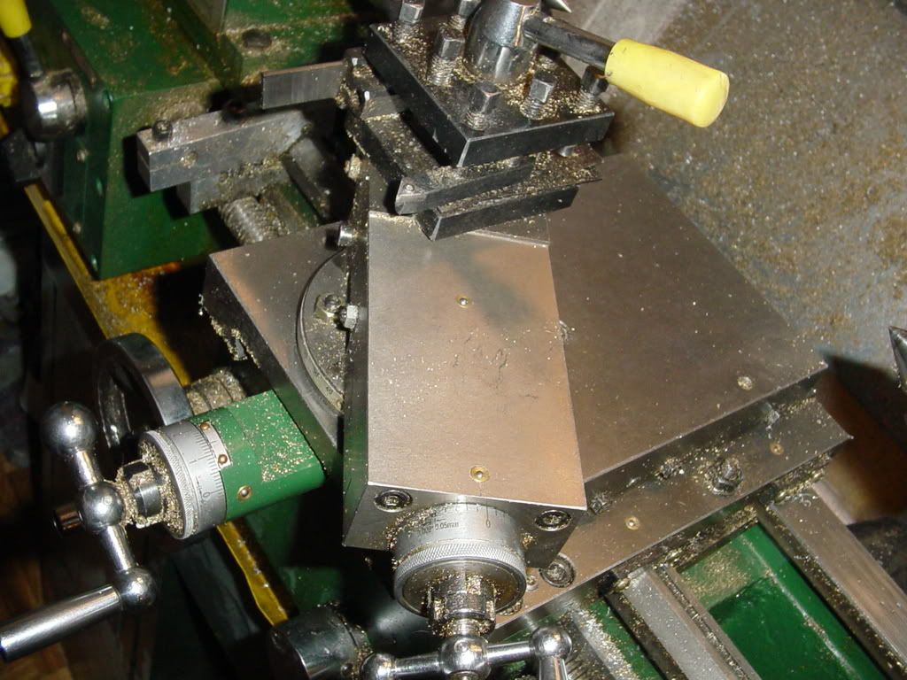
I take no credit for the designs shown in the following post. A gentleman named Steve Bedair seems to be the person who originally came up with this ball turner, and DividedHead did a couple of marvelous videos of it in operation. http://bedair.org/Ball/ball.html I have been curious about ball turners for some time, and up untill now they were a bit of a mystery to me. I am totally "Holidayed Out" today, so I spent the day studying ball turners. I took the information from a set of plans that were posted on Steve Bedairs website, and went about seeing what would have to be done to make and mount one on my specific lathe. ---And of course, since I have a bunch of carbide insert tooling with 3/8" square shanks, I designed the tool holder to suit my existing tools. Follow along if you like and perhaps you will gain a bit of insight into these marvelous tools

assy of ball turner-drawing.jpg


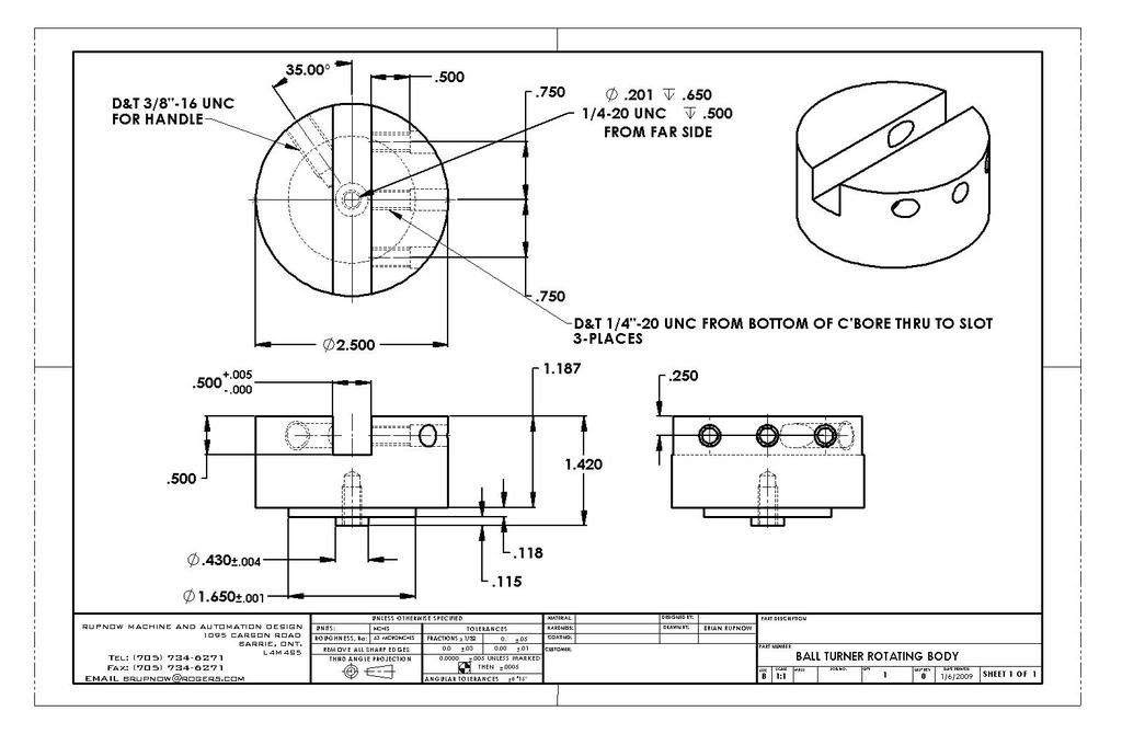
View attachment ASSY OF BALL TURNER.PDF
 
The first thing that I figured out, is that you must remove the tool post (actually, the entire compound rest) from your lathe. My lathe has a T-slot plate that can be mounted when the toolpost is removed, and at first I thought that I would have to mount the T-slot plate onto my lathe, then mount the ball turner on top of it, but no dice. The top of the T-slot plate ends up too high (too close to the centerline of the chuck) to do that, so this ball turner must mount directly to the top of the apron which the compound rest sets on. The attached .jpg shows the ball turner mounted on the lathe, and it shows the chuck with a peice in it being turned into a ball. In this particular .jpg. the tool is setting at right angles to the central axis of the lathe.

assy of ball turner-3.jpg
 
In this picture, the ball turner is swung so that the tool is setting parallel to the central axis of the lathe. The yellow plate is what gets bolted on in place of your lathes compound rest. Apparently when setting up to turn a ball, the center of the yellow plate should be lined up so that its center of rotation is "in line" with the center of the chuck, the tip of the cutting tool should be just touching the end of the part to be turned, and the distance from the yellow plates centerline to the tip of the cutting tool should be equal to the radius of the desired ball. (which is also the diameter of the round peice held in the chuck.)

assy of ball turner-4.jpg
 
This is marvelous. I can see right away how it could be set to also make convex curves and if a way could be devised to set it in circular motion as it is driven by the lathe as would be done for thread cutting, long hyperbolic curves could be made.

Or was it parabolic. I'd have to dig out my geometry books to be sure, anywho...thanks for this Brian. It really got my old thinker stinking.

:D,
Kermit
 
In this .jpg, the ball turner handle is swung towards the lathe chuck as far as it can go. The length of handle and angle at which it is attached comes into play here (you don't want to swing your knuckles into the revolving chuck!!!) Also, depending on exactly what cutting tool you use, it will reach a point where it can not be swung any farther towards the chuck, because the side of the tool will interfere with the turning peice. (Of course, you can get around that by using a tool with an offset point.)

assy of ball turner-5.jpg
 
This .jpg shows a view looking straight down on the top of the lathe, and shows all 3 positions of the ball turner relative to the chuck. Of course, the entire ball turner (except for the yellow plate) is swung though an arc from one extreme to the other by hand when cutting a ball.

assem3.jpg
 
And of course, here is an exploded view of the ball turner, in case you were wondering what was inside it and how many peices there are to it. As I said at the beginning of this thread, I take no credit for the design of this unit. I went thru this exercise today to make it clear to myself, and thought that there are probably others "out there" who would like a bit more knowledge on these really neat tools. There are a number of great posts by very talented people, and if I have helped to clarify things a little bit, then thats great.---Brian

assy of ball turner-exploded.jpg
 
Hey Brian
It's even more fun when you do it with real metal....(grin). It took me a bit to get my head wrapped around how they worked, in the beginning. I used Steve Bedair's basic premise and fitted it to the 7 x14 lathe. After a couple of false starts and a couple of odd looking balls, it all became clear. Since then I've had a ball every time I've used it. (pun intended)

Now I look for new ways to use it for both convex and concave cuts. It's made handles and hand wheels for my lathe, contours on cylinder end caps, shaped the big end of the connecting rod and a number of fittings on the Water Pressure engine and even the new shifter knob on my Jeep.

Go on.... build one and see what I mean....(grin)

Steve
 
Simply brilliant, Brian - thanks for finding, analysing and posting.

Cedge, I like the idea of doing concave cuts.
 
It seems from the picture that you need to remove the compound, not just the toolpost for that lathe. With a larger swing lathe you should be able to attach it to the compound t-slot.

I am assuming that as drawn, you would probably need to be able to shim the tool to adjust it precisely to the centerline of the axis.

My one experience with using one in school was to round off the end of a 1" brass rod. Adjusting both the center of rotation and height of the tool were pretty critical to getting a proper result, but once done it went pretty easily. I found it tricky to control how fast I swung the tool: too fast left a poor finish. I wonder if it would be possible to make a geared version similar to a rotab that would permit a slow, steady rotation of the tool.
 
kvom said:
It seems from the picture that you need to remove the compound, not just the toolpost for that lathe. With a larger swing lathe you should be able to attach it to the compound t-slot.

I am assuming that as drawn, you would probably need to be able to shim the tool to adjust it precisely to the centerline of the axis.

My one experience with using one in school was to round off the end of a 1" brass rod. Adjusting both the center of rotation and height of the tool were pretty critical to getting a proper result, but once done it went pretty easily. I found it tricky to control how fast I swung the tool: too fast left a poor finish. I wonder if it would be possible to make a geared version similar to a rotab that would permit a slow, steady rotation of the tool.

Yes, Kvom---You are correct. Sorry about any confusion from my terminology here. It is the entire compound rest along with the toolpost that has to be removed.---Brian
 
I wonder if the pivot bolt securing the rotating body to the base ever works loose. Does the Belleville washer prevent the bolt from moving in its threaded hole?

If this might be a problem, one solution is to drill and tap the bolt hole right through the rotating body and then tighten a socket grub screw down onto the end of the pivot bolt.

Just an idea.
 
Hi

I have just posted my ball turner which is designed for myford lathes over in the tools section. I have posted a bit of video as well that might help.

Cheers

Rich
 
firebird said:
Hi

I have just posted my ball turner which is designed for myford lathes over in the tools section. I have posted a bit of video as well that might help.

Cheers

Rich

Rich--I know. It was your thread that prompted me to investigate this yesterday. I see from your video that a Myford lathe has T-slots in the part directly under the cross slide (which I assume you have removed to mount the ball turner). On my Craftex lathe, there is only one circular T-slot and a plain center hole. The compound rest has a center spigot on the bottom which fits into the hole, and a circular flange with 2 holes that the T-bolts stick up through.---Brian
mylathecrossslide001.jpg
 
Hi Brian

Thats right the myford does have T slots. I think I'm right in saying that the cross slide on my lathe is an extended version and not the standard one.

Cheers

Rich
 
Brian,


Thanks for posting this. I have been looking at building one of these, and your description helps with the design to fit it on my lathe. I have a few other projects to knock out before I get to this, but it is on my short list.


Dale

 
Bernd said:
The re-invention of the ball turner. :big:

Check this old thread out - http://www.homemodelenginemachinist.com/index.php?topic=1721.0

Might give some more ideas about ball turners.

Bernd

Bernd--I did see all of those old threads while I was researching the ball turner, and I did say in my first post that I take no credit for the design. I did refer people to Steve Bedair's website. I am not attempting to reinvent anything here. I did the cad work to aquaint myself with how a ball turner would work on my own lathe, and simply put this post up as a general interest topic.---Brian
 
Back
Top