Boring head Ball/Radius turner

Home Model Engine Machinist Forum

Help Support Home Model Engine Machinist Forum:

This site may earn a commission from merchant affiliate links, including eBay, Amazon, and others.
Rod--I think that would work excellent. As far as approaching the ball--I think you have to approach it from the one end until half the ball is formed, then approach it from the other end until the other half ball is formed. As long as you set the tool height so that it matches the top of the piece when you have the handle straight up, no farther set up is necessary. Just don`t swing past center when forming either end. ---Brian

Brian, thanks, the cutting edge of this tool would be the end of the rod so it is more suited to being fed from the side. well I think that is the case. I think this replicates pretty closely what would happen if you use the same insert for turning.

Inserts are often used for ball turning but they use triangular or rhomboid inserts not square ones. I'm sure I've seen one with a triangular insert in the end of a bar for use on a boring head. The holder wasn't cranked though (why would you do that?) it was just a straight bar, although the insert may have been presented at a slight angle.

Not the one I've seen before but a similar design:

http://i207.photobucket.com/albums/bb93/blacksmithden/Radiustool-bitholder_zps24d0901a.jpg

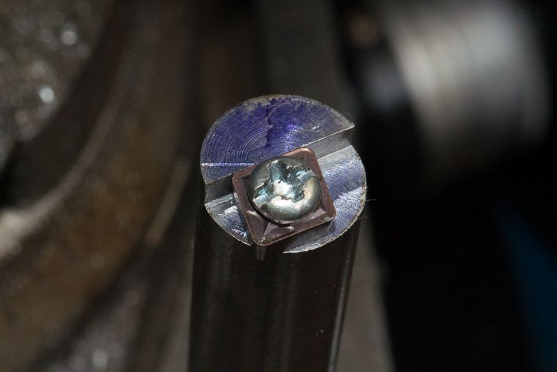
I looked at a couple of inserts I had on hand but chose the CCMT as I had a lot more of them!

The perspective of the drawing is deceiving, but the insert shown is a rhomboid shape. the tool is not actually cranked, just milled away for relief from a straight shaft. In practice, I don't think it will need to be machined as shown.

The key is to make sure the tool has the same geometry and can cut on each side. (I think). I did not want to have to order in another insert.
 
The main reason folks choose triangular or Rhomboid is to give as much clearance as possible. Square should work fine though if that's what you have.

I chose the narrow inserts for my horizontal turner but want to use HSS as well when I get round to it.

IMGP1743.jpg
 
I dropped in on my mate Chris today and checked out how he made up the insert tooling and this became so simple I did not even draw it up.

I grabbed some 12mm bar stock and stuck it in a collet and swung the vice arud to 40 degrees

DSC_5025_zpsb04bed53.jpg


The angle of the tip is 80 degrees and 40 is half of that. That means the tip is able to be aligned so the radius of the bar passes through the centre of the insert tip.

Grabbed a milling head and cut the depth to about 2.4mm, which is roughly the thickness of the tip and milled away the end of the bar.

DSC_5026_zpsb7446a31.jpg


and drilled hole which I tapped to M3
DSC_5027_zps16938db5.jpg


This is a really tight fit and the bolt has to screw into the insert.


And then I fitted the insert
DSC_5030_zps542b6fb4.jpg


I positioned the step in the rod and the hole by eye so the axis through the tool centered.

In my computer design, I milled the rod away so it was parallel with the tip. I think there is enough sticking out but if not, it is easy to fix this.

If this works, I might redo it with precise dimensions.

Sorry guys, that is as far as I got so you will wait until I try this out.
 
Well, my new tool works very well. I still approached from the side. this works fine. I think the reason is that the inset has a 7 degree relief on the back side so it is cutting out a triangular kerf so it does not bog down .

Before I used it, I scribed the edges of the insert, removed it and ground away the boring bar on my bench grinder to fully expose the sides of the cutting insert so I cold hog in the full width of the tip..

Here is the proof of the new tool. I think this is 3-4 times quicker and it leaves a much better finish.

[ame]https://www.youtube.com/watch?v=t-7Sh0iI3Mg[/ame]
 
Nice work, Rod. I'm still trying to re-configure my version to fit better on my 7x14. My first version works, but not as I want it to.

Chuck
 
The finish looks good Rod. What's the clearance like cutting the other half like?
 
Rod, I noticed you used one of those square collet blocks to hold the bit while you cut the end. I just cam down from my shop to take a break, but the last job I did was to carefully measure my square block to see if the rod is on center- it is not, by over .005" I put a drill blank in a collet and ran over it with an indicator, then rotated the block to all 4 sides. I am very unhappy to see this error but it accounts for some trouble I have had in the past that work done with the block was not accurate.

For the job you just did it would not matter, but if you expect the block to hold stock on center you had better check it.

Anyone want to buy a nice collet block, cheap? :)
 
Ron G., what type of collet block and where did you get it? I ask, because my next tool investment will be a set of ER32 collets, chucks, and a set of ER32 collet blocks.
And for RodW, what kind of lathe do you have? It may have been posted, but I missed it.

Chuck
 
I suppose it depends on how you use these blocks. .005" off wouldn't make any difference for the stuff I've done, especially since I probably zeroed each time I rotated the block anyway. I doubt I could afford a set if they were spot on.
 
Thanks for your interest guys.

The finish looks good Rod. What's the clearance like cutting the other half like?

I have not checked that but I don't expect any problems. I made a couple of measurements before I cut the boring bar to length. Its the length of the boring bar and how far back which you can get the cross slide which determines how big a ball you can cut, I made this bar a bit shorter than the one I used before so to let me move back a bit so it shoukd be able to cut a 60mm ball or so.

Rod--are you running your lathe in reverse during that video?--Brian

No Brian. After breaking my camcorder on the first video I borrowed my wife's still camera and it picked the wrong focus point which might contribute to the illusion. I think the tool geometry we both use is similar, but the difference is the relief at the back which lets mine enter from the side happilly.


Ron G., what type of collet block and where did you get it? I ask, because my next tool investment will be a set of ER32 collets, chucks, and a set of ER32 collet blocks.
And for RodW, what kind of lathe do you have? It may have been posted, but I missed it.

Chuck

Chuck, I have both ER32 and 5C collets (metric and Imperial). The lathe is an AL320G (13" swing) from http://www.machineryhouse.com.au/L141
This lathe has a 38mm spindle and I have bought the 5C block set (square and hex blocks) and a 5C collet adapter for it that threads through the spindle from the same guys. See http://www.machineryhouse.com.au/C980

I use the 5C collets in both my lathe and collet blocks but hold any milling tools in the ER32.

Most of the collets I have purchased from CTC tools but the imperial 5Cs came from Little Machine Shop. One day I will get some of the hex collets.

RonGinger, I did do some runout tests on my lathe and the collett adapter but not the collett blocks. What I found was the lathe spindle taper itself is spot on, zero runout, but the 3 jaw chuck and collets add some runout but still within acceptble specs I found on the net. I think the moral to the story is that every time you add an adapter, you add error.

I hope I answered everybody's questions. I am quite amazed with the interest this thread has aroused.
 
I do not know the source of my collet block set, I have had them for many years, but this was the first time I thought to actually measure the runout. I have used them to make a flat or rectangular shape on round parts. I was about to make the connection rod end for Gerrys Beam engine. I had made one previously but it did not come out exactly centred on teh round part, hence my checking.

I guess they are still useable if I re-zero on each surface every time I reposition the blocks. I will check the hex block later today when I get back to the shop.
 
Just an update here after a bit more playing machining the back side of the ball. The choice of screw I used impacts on clearance when feeding from the side. Because it protrudes from the front face, it fouls the spindle before you can cut do depth. With the tool in the centre position, this is not an issue. This means it will work fine if you use Brian's approach and feed the tool in longitudinally.

I tried to replace the mounting screw with a countersunk one but you would need to use an M2.5 screw as the better quality countersunk screw I had was too big to fit through the insert tip. If you use the correct screw for the insert tip, there will be no clearance issues as the flat face of the tool will allow the cutting tip to touch the spindle.

When I get to it, I will redraw it with some accurate dimensions and make a new tool based on my learnings.

The finish I achieved today was fantastic and I was able to proceed quickly to a mirror finish skipping the 240 grit I used previously and starting at 400 grit wet and dry.
 
I do not know the source of my collet block set, I have had them for many years, but this was the first time I thought to actually measure the runout. I have used them to make a flat or rectangular shape on round parts. I was about to make the connection rod end for Gerrys Beam engine. I had made one previously but it did not come out exactly centred on teh round part, hence my checking.

I guess they are still useable if I re-zero on each surface every time I reposition the blocks. I will check the hex block later today when I get back to the shop.

I might try setting mine up in my vice and see what the coaxial indicator says as I rotate the blocks. I guess if you know the error, you'd only need to offset the mill table a smidgen. Maybe stamp the adjustment on them.
 
Hi
One thing that I observe watching video of a "Boring Bar - Ball Turner" is that moving the cross slide to the bar stock in the chuck gives some horrible angles for the tool tip to work to.
Not until the tool is advanced to be on centre line both vertical and horizontal does it peel off a continued chip stream.
""Omnimill"" with a vertical piviot is a different story with no change in the cutting angle attack.
Surely for the "Boring Bar" approach is the the piviot must move down on to the work on the vertical plane having the boring bar Piviot mounted in a Vertical slide and on vertical centre line.
OR
Advance by adjusting the boring bar radius closer to the centre of it's piviot until the desired diameter is reached.

Eric
 
Last edited:
I do not know the source of my collet block set, I have had them for many years, but this was the first time I thought to actually measure the runout. I have used them to make a flat or rectangular shape on round parts. I was about to make the connection rod end for Gerrys Beam engine. I had made one previously but it did not come out exactly centred on teh round part, hence my checking.

I guess they are still useable if I re-zero on each surface every time I reposition the blocks. I will check the hex block later today when I get back to the shop.


If anybody does have a source for accurate collet blocks please inform the group. I've run into similar problems pith a set of collet block I have.


Sent from my iPad using Model Engines
 
I have been using boring heads to make knobs for years. However I use a mill, boring head, and an indexer. You set the boring head with cutter turned inboard same as you would to "turn" a post. You set the indexer at the angle where the apex of sphere and diameter of shaft holding your work piece so they are on the same plane. Edge find the piece so you are centered in the full sphere axis and centered less the chord of circle in the axis with shaft sticking out. Turn the mill on in reverse (cutter is facing inboard remember) lower qwill into work a bit, and index 360. Repeat until you have a sphere. Variations of this can produce acorn shapes, dished edges and other artistic designs. You must be gentile, as if too aggressive you can unscrew the boring head from its adapter. I would assume the same could be done in the lathe with the boring head in the chuck and using the compound to set the angle, provided you have a provision to rotate the work piece.
 
Just a bit of an update after I have cut a few more radiuses. I think Brian is right. It is better to centre the tool and approach along the Longitudinal axis. I found it is pretty easy to zero my DRO with the ball turner in its final position so I know when I have advanced into the ball enough but a carriage stop would also be useful.

Finally, my polishing has progressed a bit. Yesterday, I just used wet and dry sand paper with the coolant trickling on the part instead of kerosene as a lubricant. There was no difference in the final result though.

Finally if you have a ball on a threaded mandrel and you can't remove it after turning and polishing, try wrapping the part in Glad Wrap (eg. Cling wrap). Worked a treat and let me get a good grip without marring the finish.

I made myself a coffee tamper yesterday and it came up a treat in polished aluminium. Two pieces with a threaded handle. I bought a piece of stainless steel bar today and have ordered some turning and parting inserts to see if I can remake the base in stainless steel. $300 a metre Ouch! Anyway, I only bought 150mm (6"). The tricky bit will be to centre drill and tap a hole in the base for the handle to screw into. I ordered an ER32 tapping collet that has a built in clutch to prevent breaking a tap when it bottoms out so I might mount the base in my rotary table chuck and try drilling and tapping on my SX3 mill. I'll post some pics of the completed part as the tapered handle is a really nice idea if you want something different.
 

Latest posts

Back
Top