BALL TURNER MYSTERIES UNVEILED!!!

Home Model Engine Machinist Forum

Help Support Home Model Engine Machinist Forum:

This site may earn a commission from merchant affiliate links, including eBay, Amazon, and others.
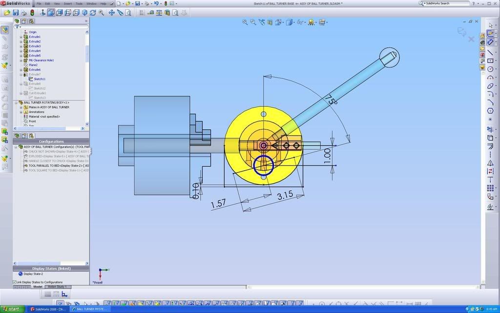
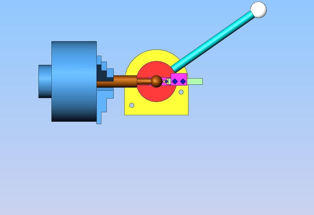
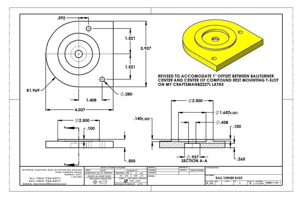
This is a drawing of the base, pretty well the same as Steve Bedairs. Keep in mind, however,as per the main general arrangement drawing at the beginning of this post, the hole centers and diameter and O.D. of the part are suited to my specific lathe. If your lathe is not a Craftex B2227L, then these dimensions will have to be changed to suit your own lathe.
ballturnerbase.jpg


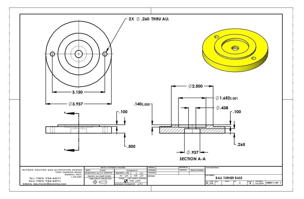
View attachment BALL TURNER BASE.PDF
 
And last, but certainly not least, the tool holder. Again, keep in mind that this design is very specific to my Craftex lathe, and to a inserted carbide tool with a 3/8" square shank on it. The height of this peice is critical---Again, as per the main General Arrangement drawing at the very beginning of this post, the height from the underside of the ball turner base to the top of the cutting tool must match the distance from the mounting surface on your cross slide up to the centerline of your chuck.
toolholder-1.jpg


View attachment TOOL HOLDER.PDF
 
I made the handle from 1/2" diameter round cold rolled x 7 1/4" long with a 3/8"-16 unc thread x 5/8" long on each end, and a 1" diameter ball. The handle might have to be heated and bent to clear obstructions on your lathe, or to be in a more ergonomic position for you.
 
Brian Rupnow said:
I did say in my first post that I take no credit for the design.

I didn't mention anything about who took credit.

I did refer people to Steve Bedair's website.

That was also mentioned in that thread. ::)

I am not attempting to reinvent anything here.

Don't look that way from my side of the fence. :big:

I did the cad work to aquaint myself with how a ball turner would work on my own lathe, and simply put this post up as a general interest topic.---Brian

I built one to see how it works. ;D
 
Bernd---I'm setting around here on my arse with no work, waiting for the phone to ring. I am curious about ball turners, and I admire you if you built one to see how they worked. Different strokes for different folks. I would rather do it on the computer to "see if it works" than machine parts and then send them to the scrap bin because they didn't work. why are you raggin' on me?
 
I am assuming the Craftex is like a seig C2 style lathe.

A couple of places to get some ideas on how to mount that up

One that I started for a C2

GadgetBuilders ball turner. Where I got my inspiration from.

Eric
 
Okay---Let the games begin!!! I just went down to my local metal supplier and spent $10.87 for enough stock to build the ball turner and a chunk of 1" O.D. aluminum to make a ball from.
MATERIAL001.jpg
 
ligthen up guys brian has done a great service to this site for the time i have been here he shares and has great talant that we can all learn from I will never understand people. We should all be greatful when someone is willing to share an idea and make it so anyone can understand if you think making a draw in cad is easy good luck the pics that brian has done for all of use would cost use dearly if we had to pay. enough said I am so pissed off now
I can't believe it.
 
Just a couple of points;

Someone suggested milling a slot in the side of the tool head, where the pinch screws in the body bear on it - I did that and it is, IMHO, a very worthwhile mod.

I build two tool heads for mine - one 'normal' for convex turning, and one 'back to front' for concave.

I hacked up a 6" rule and used bits of it to put little scales on the feet of the tool heads. (oos, that's three)
 
tel said:
Just a couple of points;

Someone suggested milling a slot in the side of the tool head, where the pinch screws in the body bear on it - I did that and it is, IMHO, a very worthwhile mod.

I build two tool heads for mine - one 'normal' for convex turning, and one 'back to front' for concave.

I hacked up a 6" rule and used bits of it to put little scales on the feet of the tool heads. (oos, that's three)

Yes Tel, your right about the relief in the side of the tool holder. I missed that. I will add it to my drawings,---Brian
 
Brian
The slot will help things a bit, but my next one will also have a brass strip in the slot to keep the screws ends from buggering up the aluminum. I've got to build another one for the C4 lathe. The original one wont bolt to the slots in the cross slide and its a wee bit short of the center line.

Bernd...
Easy there amigo... I like "machining with digits" first, myself. Nothing wrong with wasting a bunch of 1's and 0's before one begins cutting metal. Sure saves on buying a larger scrap bin. I don't think I saw anyone stealing any credit... I did see someone sharing the fruits..... and the credits.

Artrans....
Ah... Never mind....LOL. It's just part of life on an online forum. Getting a hornet in one's bloomers just happens from time to time.

Steve
 
Cedge said:
Bernd...
Easy there amigo... I like "machining with digits" first, myself. Nothing wrong with wasting a bunch of 1's and 0's before one begins cutting metal.

Makes you wonder how they built machines before computer's don't you think? :big:

Sure saves on buying a larger scrap bin.

Don't need a scrap bin, I just reuse the part on something else, although it may be a bit smaller. Very little scarp. But then I don't do much either, just ask the wife. ::) :big: :big:

I don't think I saw anyone stealing any credit... I did see someone sharing the fruits..... and the credits.

Could you quote me were I said that please?

That's all. Good night.

Bernd
 
Bernd....
I'm going let it all slide and chalk it up to a bad day in your world.

Steve
skid marks on his fingertips.
 
I have identified a problem with my planned build. The attached picture shows the cross slide of my lathe cranked in to its maximum position. As you can see, the center of my circular T-slot does not reach the centerline of my lathe chuck. In fact, it lacks an inch of going far enough. This will have to be remedied so that I can reach the position shown in the attached solid model. To rectify this situation, I am going to have to modify the ball turner base, to allow the center of the ball turner to be offset by an inch from the center of the circular T-slot in order to be able to set this tool up properly.
PROBLEM002.jpg

assyofballturner-4.jpg
 
This layout shows the changes necessary to the ball turner baseplate. The 1.00" dimension is the offset from the centerline of the ball turner pivot to the center of my circular T-slot, and it also shows the position of the new mounting holes. The heavy blue circle shows where the center of my circular T-slot will now be.
layout-2.jpg
 
Might be a blessing in disguise. You move the cross slide to its full extension and you're automagically lined up on the axis.
 
The change in the ball turner baseplate will now let me achieve this position, which is critical to be able to make a perfect ball and not an ogive. (which is a kind of oval with pointy ends).
newposition.jpg
 
Heres a ball turner mystery for you all.What came first the ball turner or the ball on the end of the ball turner handle?

best regards Steve C
 
Back
Top