A new engine for fall---

Home Model Engine Machinist Forum

Help Support Home Model Engine Machinist Forum:

This site may earn a commission from merchant affiliate links, including eBay, Amazon, and others.
So here we have it, gentlemen- The material (or at least most of it) for my new engine. The thick slab of bronze is destined to become a flywheel. The thin piece will become trim pieces such as the tappet guide. The steel flatbar in two different thicknesses will become crankshaft webs. the large aluminum block will become the crankcase, the two smaller blocks will become combustion chamber immediately below the cylinder head and the backplate. I have enough round steel stock on hand to make the crankshaft from. I have yet to purchase the cast iron for the cylinder and the piece of aluminum which will become the baseplate. My supplier with the giant size self feeding bandsaw charges me $10 per slice through the bronze, so I think the total price came to around $35.00 for material.
 
Mystery Solved----Kind of---I chucked up a piece of cold rolled round stock in my rotary table/3 jaw chuck, put the #4 gearcutter back in the mill, and took a full depth 0.090" cut. The gearcutter was shrieking at a "normal" speed for this kind of work, and I was again getting sparks off the cutter. ---And that was WITH cutting oil. A close examination of the cut cold rolled shows material being "extruded" around the sides and end of the cutter path. I have concluded that the gear cutter was duller than a hoe!!! It probably wasn't the fault of the 1144 stress proof material after all. Some ham-handed bugger who uses my mill MAY have run the cutter up against a hardened jaw on the 3 jaw chuck the last time the cutter was used and put away. I don't recall doing it, but I am the only person who ever works in my little home machine shop.:wall::wall: Anyways, a quick phone call to Travers in South Carolina, and I am $60 poorer and a new cutter is coming UPS.---Brian
 
Last edited:
Hey Brian have you checked out KBC tools there is one in Mississauga, they have both high and lower quality tools and equipment. And prices are responsible
 
Hey Brian have you checked out KBC tools there is one in Mississauga...

I was going to suggest exact same & additionally - you are a brave man to ship UPS to Canada (unless they have some special arrangement like Amazon dot com). An envelope of air can cost you $40 in UPS 'processing fees' over & above shipping, Gst, Pst, Bendoverformore-t etc.

Travers has a CDN distributorship too do they not?
http://www.traverscanadacatalogs.com/

Anyway, here is KBC cutter screen grab & links
http://www.kbctools.com/can/main.cfm

SNAG-0047.jpg
 
KBC is great I order everything on line then go pick it up, they will ship too.
 
One burning question remained--On the cast iron cylinder, due to very close clearances and constraints, I ended up with a #5-40 tapped hole 0.079" off the side of the cast iron part. I wasn't sure if I could do that or not without the thread breaking out thru the face. This set-up answers my question, and it's an answer I didn't want to hear. There is still enough thread in the cast iron to hold sufficiently, but it looks crappy. My next stunt will be to drill and tap the hole .188 back from the edge, and then machine material away until I have my .079" edge to center distance and see what that looks like.
 
And the short answer is---that doesn't work either!! The thread still breaks thru. This is going to call for a small design change on the affected drawings.--Brian
 
Okay!!! At 0.095" edge distance, we are golden!!! No break out of the threads thru the side at that edge distance. I will write that on my wall of "things to remember" and make the slight design change to my drawings.---Brian
 
And so it begins---Once I had the outsides of the block milled to size, I set it up in the 4 jaw chuck and drilled a hole all the way through, and reamed it to 7/16" diameter. I then proceeded to use a series of drills to go part way through the block, until I topped out a at my 1" Silver and Demmings drill. Then it was boring to the proper depth and diameter. That finished hole that goes all the way thru will eventually be reamed to 0.5" for a bushing, but since I want to "align-bore" all of the plates together to get the bores all in exact alignment, that 7/16" reamed hole will act as a set-up hole when I get to that point.
 
Ok. I see chips flying. Another Rupnow build has commenced. I have my chair pulled up and the coffee is on.
good luck and godspeed
 
I just about got caught!!! I finished up the two main bores in the crankcase, and just as I was finishing the hole thru the top for the con rod and cylinder base, I began wondering if I had checked for side clearance on the rod where it comes thru the hole in the top of the crankcase. I opened up the 3D cad model to take a look, and it's a good thing I did. What I had forgotten was that the big end of the con rod actually extends beyond the crankshaft web/counterweight, and there would have been a big time interference. I had to set the crank case back up in the 4 jaw (I hate that) and relieve a center path all around to clear the con rod big end. I took a couple of pictures while things were still set up to try and show the additional path I had to create. The original bore I had put in would have cleared the crankshaft web/counterweights with .030" radial clearance, but not the con rod big end.


I will post a download to all of the drawings for this engine as .pdf files for those who would like to build it. I used to post the drawings as I was building the parts, but experience has shown me that I "tweak" the drawings so much as I go along to show what actually is made in metal, that I would have to repost the same drawing 3 or even 4 times. This drives everyone a bit mad, and there is too much chance of people not saving the newest "revision" and making bad parts. I am always thrilled when people build one of my engines, but it is a much safer thing to wait until I have a running engine with all of the drawings up to date before I post the link. I do enjoy the comentary and hearing the opinions of other folks as I work my way through a project, so please don't be shy. Stop and say Hi---It lets me know that people are interested and following the thread.---Brian
 
Hi Brian, I've always enjoyed following along your journey


Jeff
 
I'm a fan of all your builds Brian and I'll be following along eagerly. I'm sure I'll build another of your engines at some point, but my next project will take quite a while.
 
You always surprise me Brian with your ability to design and build so many engines, I'm following along with great interest.

Paul.
 
Well, if you squint your eyes real hard, and look at it just the right way, it's beginning to look like an engine.At least all the big parts bolt together.---That's a good start.!!!---Brian

 
Things are going together remarkably well, so far. I had a bit of problem with gear mesh between the crank gear and the jockey gear, but I am sure its something that a bit of a run in with carborundum paste will fix quickly.Probably the next thing I build will be the large bearing support which registers and bolts to the large hole in the side of the crank case.---Brian

 
Looking good Brian and coming together fast.
I like your drawing it’s sure easy to tell the WORKING copy from the FILE copy.
Keep up the good work
 
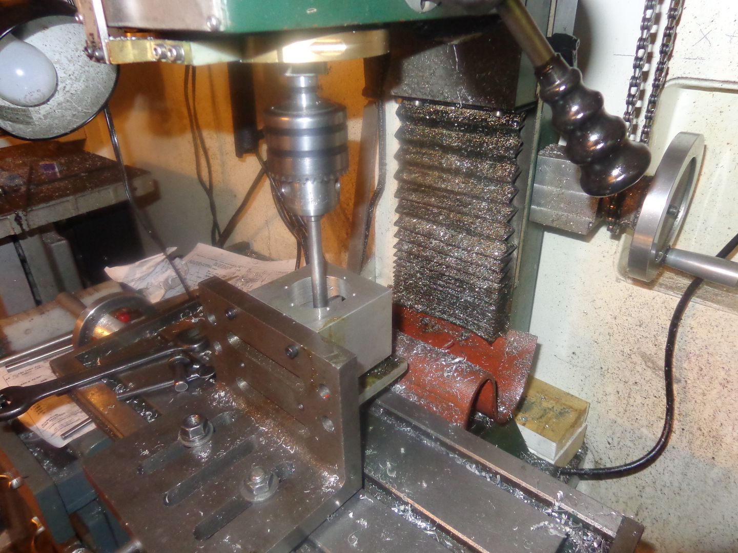
So---what do you do with sticky gears??---Well, if you live at my house you find a way to "unsticky" them. There are a host of different reasons that gear trains can be sticky---some can be fixed without setting the gears back up in the rotary table/mill and recutting them, and some can't. If the shaft centers for the shafts supporting the gears are not drilled the correct distance apart, well, you're toast. Nothing can fix that except maybe, if you are very very lucky you can SOMETIMES take a very small cut off the o.d. of the gears, to prevent the tip of the tooth on one gear from bottoming out on the root of the other gear, if the holes are drilled a few thou too close together. If the holes are too far apart, the gears will work, but will be noisy. If ya don't believe me, you can ask Chuck Fellows about that one. Sometimes gears are sticky even when the shaft centers are drilled "Right on". That can be put down to the tooth form being off a little bit, or a bit of spring in the arbor when the gears are being cut. Sometimes it seems to be just plain orneryness (if that's a word). About half the time, the gears I cut run together perfectly. The other half the time---well---If I can get the gears to turn at all (meaning they aren't locked up solid with each other). I cover the faces with a bit of 300 to 400 grit carborundum paste and put some power to them. Not for long, and not too fast, because that stuff cuts fast, and we don't want gears with pointy teeth!!! I recommend a rotating speed of about 300 rpm, and a time of about 15 minutes. If they aren't "unstickied" by then, run them in reverse for the same amount of time. The carborundum paste works very well, and once you can turn the gears freely by hand, take everything apart and wash everything really well with Varsol or a similar solvent. If you are still not 100% happy with the way they mesh, then cover everything with a good slather of grease, set them up with a power source, and let them run for an hour or two. The set-up in my attached picture shows the engine I am building with all 4 gears in place, covered with grease, and running in my milling machine. They turn very freely now, and should give trouble free service when I get the engine finished. The crankshaft gear is cut from cold rolled steel, the jockey gear is cut from cast iron, and the two large gears for the cams are cut from 1144 stress proof material. As I said in an earlier post, spur gears can be very noisy when running on a small engine with no gear cover. The gear cover serves two functions, one being to keep a good supply of grease around the gears, and another equally important reason is to keep the sound of the gears meshing contained.
 

Latest posts

Back
Top