A new engine for fall---

Home Model Engine Machinist Forum

Help Support Home Model Engine Machinist Forum:

This site may earn a commission from merchant affiliate links, including eBay, Amazon, and others.
The new engine looks like a great design, but I can't help thinking that a lot of the cooling is wasted on the lower 3/4 of the engine.

Paul.
 
As I have said before, I plan on using "sealed" roller (not ball) bearings on both ends of the con rod and "sealed' ball bearings on the load bearing side of the crankshaft. That is why the crank is split into two halves. Since the bearings are filled with grease and "sealed" I shouldn't have to lubricate the rod nor the crankshaft bearings. The more I look at it, the uglier it gets with that big flywheel on it.--I'm not too concerned about the airflow---the airflow hitting against the side of the crankcase will be forced out to the sides and "up and over" the cooling fins. I think I will probably go with a 4" diameter flywheel and a separate fan setting above it. That simplifies the flywheel by an order of magnitude, and I can probably utilize the computer fan/propeller that I bought for the Jaguar and then didn't use, driving it with an o-ring drive belt.--That will also direct more of the air across the cylinder and head.
 
Hi Brian
If your into a little sheet metal work to form a shroud you might want to have a look at set up b.lindsey used on his Briggs & Stratton 6S build.

http://www.homemodelenginemachinist.com/showthread.php?t=5343&highlight=brigs&page=13

IMG_0071.JPG
 
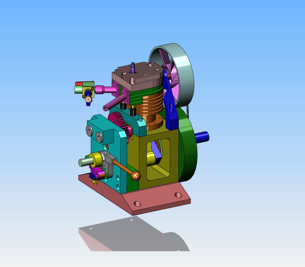
I have a few minor logistics to figure out yet, but here is the engine with a 4" diameter flywheel and the 2 15/16" diameter computer fan I bought for a previous engine and then didn't use. As far as I'm concerned, this is a really big improvement over the 7" flywheel/fan.
 
Okay Folks--It's opinion pole time!!! This morning as I was going through the model adding all of the bolt holes, I decided I didn't like those yellow angle end supports. A bit of quick modelling gave me the flat plate base as you see it here to support the engine instead of the angle plates. Since the engine has a dry sump, I don't have to contain any oil in the crankcase. True, it exposes the spinning crankshaft and con rod, but any-one who sticks their finger in there would pretty well have to do it on purpose. I like this new base better. I want to know what you guys think. Do you like this plate base better or the yellow angles as in previous versions I have posted.
 
Lets make it 3 - 0 for the base plate, nice clean look.

On a side note, (and you brought it up ;D) if we’re talking appearance as far as the open crank case goes, the more moving parts you can see the better. The engine below might be a wonderful engine but being a fully enclosed water cooled engine with nothing moving but the flywheel, it’s not going to be very interesting to watch run.
Just my 2 cents (plus GST,PST, VAT etc.)

Untitled.jpg
 
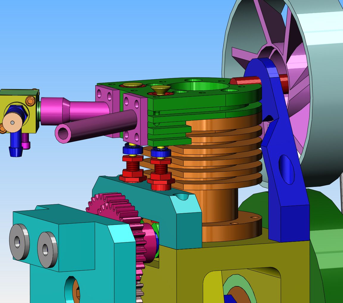
For those of you who have been asking about how I will adjust the valve lash on this engine----This is it. The "tappets" will be of 3 piece construction, having an internally tapped bottom that will ride on the cam, an externally threaded top section which rides against the end of the valve, and a lock nut. The bottom section of the tappet is 5/16" diameter, and is hardened "01" steel. the top portion will also be hardened "01" steel. The internal thread is a #10-24. I left the cylinder head off in this model so you can see that I plan on using pressed in valve cages.----Brian
 
Well Sir!! I think that just about covers it!!! Oh, I've got to so something about a place for my started spud so I can use my variable speed drill as a starter, and probably add a few keyways and bolt holes, but I think the overall design is 99% done. everything on there I have built before on my previous 7 i.c. engines, except for perhaps the adjustable tappets----and that doesn't look like brain surgery. I think this will be a really neat project for a new engine this fall, and as usual I will be posting the engineering drawings fro anyone who wants to join in the fun. I guess my next step will be to make a list of all the bushings and bearings and go have a chat with my bearing supplier.---Brian
 
Brian,

I bow (very low) to your design experience and many years of building things, but I wonder if more than 24 tpi on your valve adjusters would make fine adjustment easier. I also realize that maybe the courser thread is needed for strength.

Just Wondering,

--ShopShoe
 
ShopShoe---The decision to go with #10-24 thread had a lot more to do with what taps and dies I have available than any sound engineering principles. Either thread will work adequately. It's one of those things that will probably be adjusted once and then never again. Non of these little engines run long enough periods of time to wear down the valve seat and face to the point where they need much lash adjustment after it is first set. Of course, the key factor is to be able to set it the very first time.----Brian
 
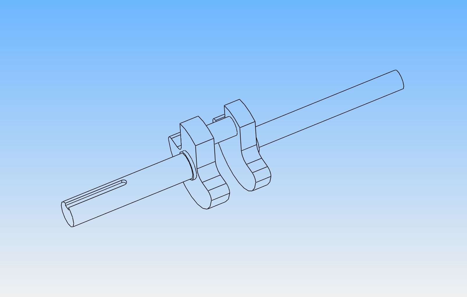
I am going to "borrow" the crankshaft design from Malcolm Stride's "Lynx" engine. The crankshaft will be made up from individual components which will be silver soldered together. However it will remain as two totally separate assemblies. The 1/2" shaft with keyway, the counterweight/web and the 1/2" diameter rod journal will be one assembly. The other end of the crankshaft will be 3/8" diameter and consist of only the shaft and the counterweight/web. This second counterweight/web will have a 1/2" hole reamed through it, which the rod journal will pass completely through, ending flush with the other side of the counterweight/web. The rod journal will be made from "01" water hardening steel, which will be quenched immediately after silver soldering to harden it. Both ends of the full crankshaft will be supported by two bearings, to prevent any potential misalignment. (The crankcase and outboard bearing support will be assembled, doweled, and all bored in one set-up.) This arrangement will allow me to use a sealed roller bearing on the big end of the con-rod. The width between the counterweight/webs when all is assembled is sufficient to allow a .015" thick spacer washer on each side of the con rod bearing.
 
Brian,
If you get the rod journal hot enough to quench and harden it you will have cooked all the life out of the silver solder. If you want a hardened pin you're better off to do it first and press it into the crank cheek. A lot of motorcycle (singles through triples) have assembled cranks. I have rebuilt singles many times. The pin is pressed into one cheek and is set up to press the other cheek on by using a straight edge to get it started square. It's then pressed home and mounted on a fixture so that it can be spun with dial indicators resting on the shafts. To true it up one only needs to clamp one cheek and tap on the other to move it around the rod pin. The assembly is then again indicated. It doesn't take much to true them up.
O-1 steel is oil hardening. W-1 is water hardening.
gbritnell
 
Yes, I tend to agree with George, the bright red you need for hardening is a long way above the dull red needed for the solder. There is also the fact that the clearance needed for teh solder to wick into the joint may throw the pin off line.

Its not to hard to press one in, I have done it in the past using my mill vice to keep things nice and square, this ones been upto 8500rpm. If I remember rightly its a 7/32" pin into a 5.5mm hole

J

IMAG0693.jpg


IMAG0694.jpg


IMAG0695.jpg
 
Okay Gentlemen--I defer to your knowledge. I was thinking the same thing last night. I will press the crank together How about if I solder the counterweight/web to the crankshaft , then harden the pin by itself, then press the hardened pin into place in the counterweight web? My webs are not terribly thick.
 
Last edited:
Should be OK doing that. I would solder it up then put it back in the lathe, skim the end and drill/bore the pin hole, that way you can make sure the pin is true to the main shaft even if the web gets soldered a bit out of line.

J
 
Back
Top