A new engine for fall---

Home Model Engine Machinist Forum

Help Support Home Model Engine Machinist Forum:

This site may earn a commission from merchant affiliate links, including eBay, Amazon, and others.
It may not be impossible to have a side valve engine with dual independent cams machined from barstock, but it's damn difficult!! This configuration looks interesting.

 
Brian ,not sure what info is available but Dick Upshur had plans for something similar to this. It was a representation of a palmer zr1 made in Cos Cob Conn. Made around 1925 and it was a marine engine. Called a T head marine engine and it had two cams and a valve on each side of the cylinder. These are supposedly very efficient because the gas charge does not change direction.
 
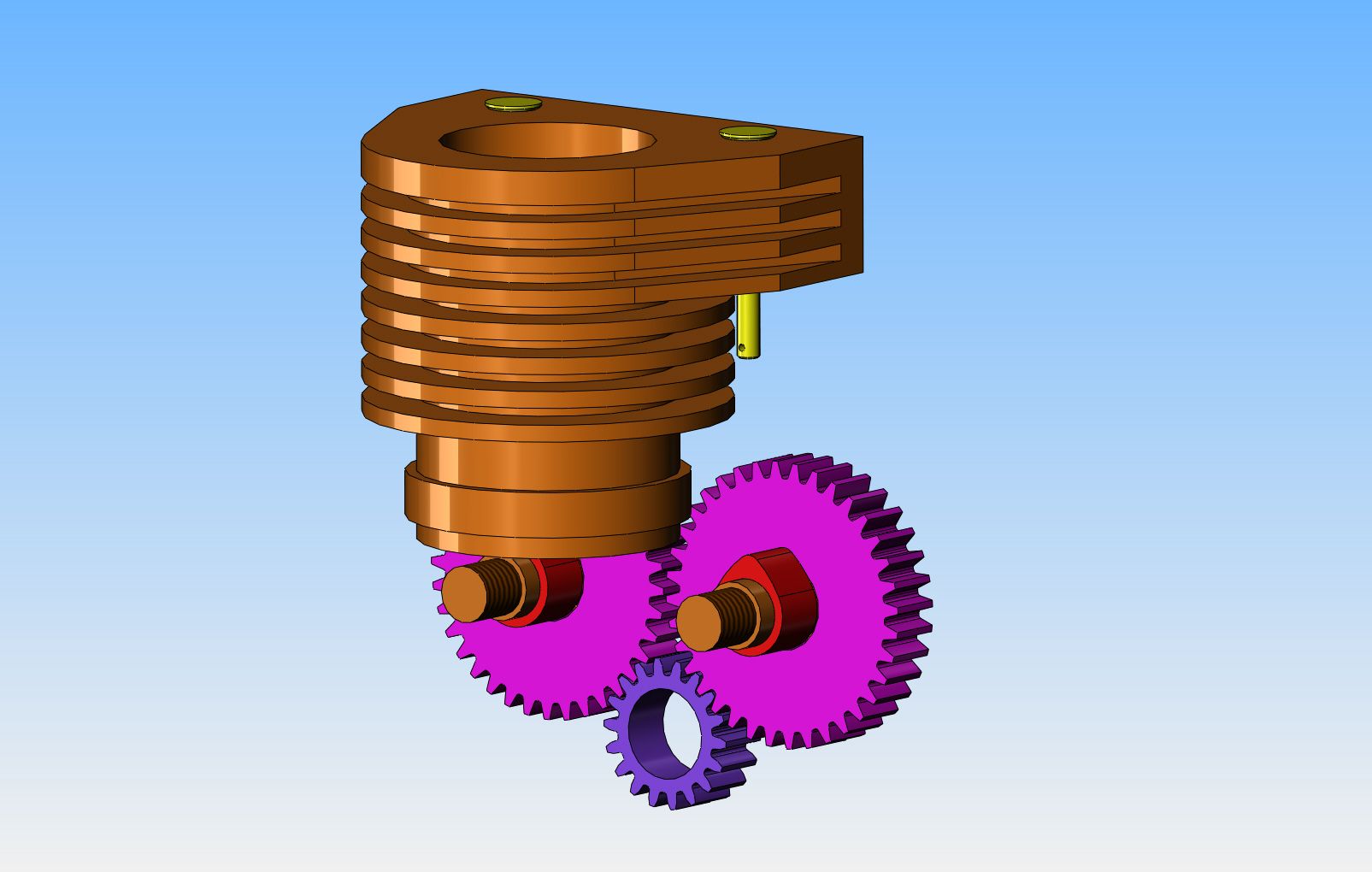
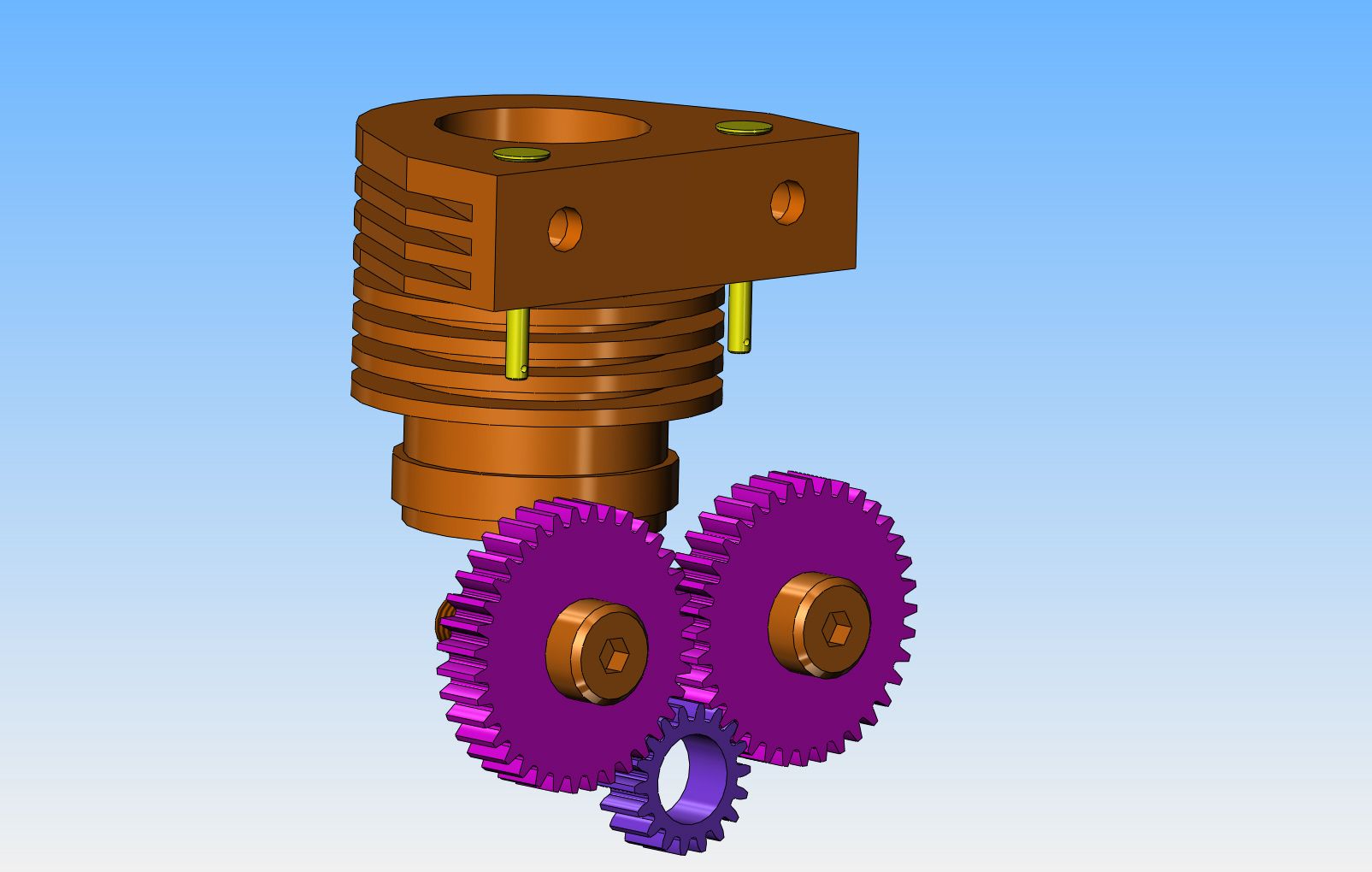
Thanks Steve. Jason from another forum has suggested staggering the cam gears and making the crank gear longer. That would allow me to pull the valves in closer together and consequently have a smaller overall cylinder width with shorter runners between the valve and the combustion chamber. He also suggested making the crankshaft 3/8" diameter on the end which operates the cam gears, allowing for an overall reduction in gear diameters. Right now, with a 1/2" diameter end on the crankshaft, the gear shown is the smallest gear that will go on a 1/2" shaft, and the cam gears have to be twice that diameter.--Very clever!!! I don't think Dick Upshur is still alive, and I don't really want to pay whoever now owns rights to his drawings for another set of plans.----Brian
 
The valves on the t head are on opposite sides of the cylinder. Dont worry about buying plans. look up palmer zr1 marine engine and you probably will get pictures that you can get ideas from.
 
Indian used a different arrangement 1 cam lobe operating both Inlet and Exhaust valve

Scout Lifts in Case.jpg
 
I think this could work---The cyan blue backplate would be 3/8" steel with 3 steel stub shafts welded into it. It would attach with 6 bolts and two locating dowels (not shown) to the dark green spacer bar, which is itself bolted and dowelled to the aluminum crankcase. The gears and cams might be machined from bronze or cast iron, something with enough lubricity that they can rotate on the fixed shafts without galling. The con rod has sealed needle bearings in both ends, the dark blue half of the split crankshaft has two sealed ball bearings supporting the end where the flywheel goes. The "follower half" of the split crankshaft would run in bronze bushings. The blue bridge which spans across the top of the aluminum crankcase is the tappet guide, and could be aluminum.


Last edited:
Okay!!---I am happy with everything here, and know it will work. The only "grey" area is attaching the valve body to the cylinder and the cylinder to the crankcase.--I haven't spent any time thinking about the flywheel, and I am pretty certain that like the Jaguar/Canadian Cub engine that I just built, this one will need a built in fan for cooling. The exhaust will be simply a screw-in straight pipe, and the carburetor will either be a copy of the Jaguar carb or my version of the George Britnell carb clone.
 
Brian, I like your idea of using a follower on the crankshaft to work the gears, the dark blue crankshaft is well supported.

Paul.
 
I gave up on the idea of having a steel backplate with welded in stubshafts. Last night I lay in bed thinking, and I had originally intended to solder the cams onto the face of the gears. This is always a somewhat "iffy" proposition, and as I have said all along, I want to be able to adjust the cam timing independent of the gear teeth. I decided I would be able to do that if I added a hub and set screws to one side of the gears and silver soldered the cams to the 3/8" shaft, while leaving the gears free to rotate into whatever position I wanted them to be in relation to the cam position, then lock them to the shaft with the set screws in the gear hub. This means of course, that the shafts must now be able to rotate. So---I changed the steel plate to an aluminum plate, with two 1" long oilite bronze bushings pressed into the thick part of the plate. The blue circles you see are the heads on the ends of the two cam shafts. They need shallow heads on them to keep then from trying to pull out of the bushings as they revolve. The other end of the camshafts which support the gears and the cams is still cantilevered, but it's only a 7/8" cantilever from the edge of the aluminum plate out to the centerline of the cams, so I don't anticipate any bending. The jockey gear is made from bronze and rotates on a 3/8" steel shoulder bolt which screws into the side of the crank case.
 
We have to get a set of my favourite Chrysler product ignition points mounted somewhere, and since we are in the design phase, I might as well mount them on an adjustable plate so I can adjust the ignition timing while the engine is running. That is easy enough to do by extending the end of the outer crankshaft bushing and bumping up the extended diameter to 5/8". I can then clamp the ignition points mounting plate onto the head of the bushing.
 
Now my engine can breath in and breath out----As you may have already figured out, this will be a "dry sump" engine, with sealed ball and roller bearings on the load bearing side of the crankshaft and in the connecting rod. The non load bearing side of the crankshaft is supported in "oilite" bronze bushings, as are the cam shafts, and gears. They will get a bit of oil from an oilcan when I run the engine. Tomorrow I will decide how I am going to support the engine, and what to do for a flywheel. I have thought about going to a 7" diameter flywheel with built in "fan-blades" to provide a steady draft of air over the cooling fins on the engine. I will have to model it and see if it looks reasonable or ridiculous.
 
This is the point at which things begin to get a bit----goofy? The engine needs a flywheel. Past experience has proven to me beyond a doubt that the larger diameter a flywheel is, the better the engine will run and idle. Throttle response won't be as quick, because that's a lot of mass to move, but if fast throttle response isn't vitally important, then a large diameter flywheel is the way to go.
The flywheel shown is 7" diameter, which is about 1" too much in my opinion, to keep the proportions reasonable.----So----Why make the flywheel so big?--Because a second factor I have proven to myself, is that without some kind of airflow over the fins, the engine will rapidly overheat. All you guys who build these small engines with a propeller, like for instance the Nemett series by Malcolm Stride will know how much the air from the prop will cool the engines. I don't like propellers.---Having once, in my jaded past, stuck a finger into a (thankfully small) propeller on a model gas airplane, I HATE propellers. So---What to do?--I need a flywheel anyways, it has to be made from steel (can't afford brass) and I can weld steel. ----By making the flywheel 1" larger in diameter, and drilling 5 holes through the web, I can then make up 5 blades of .125" thick steel and weld them into the holes at a 45 degree angle. This will create lots of air movement, yet the flywheel will have a smooth outer rim in case some poor fool like me inadvertantly touches it. It will work. In fact, I think it will work very well. The only downside is that it makes the engine look "goofy".


This is a very good example of engine size comparisons. The engine on the left is patterned after the Nemett Jagauar, an engine having a 7/8" bore and a 3" diameter flywheel. The engine on the right is my new side valve engine with a 1" bore and a 7" diameter flywheel. The basic engines are very close to the same size. The new engine with the large flywheel has to have the support angle feet extended a long ways so the bottom of the flywheel will clear the table. Of course, I had to add a belt driven fan to the Nemett engine to get it to run cool enough, so it was extra work to make the fan, fan housing, blade, shaft, bushings, etcetera. I like the proportions of the Nemett engine a lot better.--Decisions--decisions---
 

Latest posts

Back
Top