90 degree V-twin engine

Home Model Engine Machinist Forum

Help Support Home Model Engine Machinist Forum:

This site may earn a commission from merchant affiliate links, including eBay, Amazon, and others.
Looks great George!

Thanks for sharing that..... :bow:
 
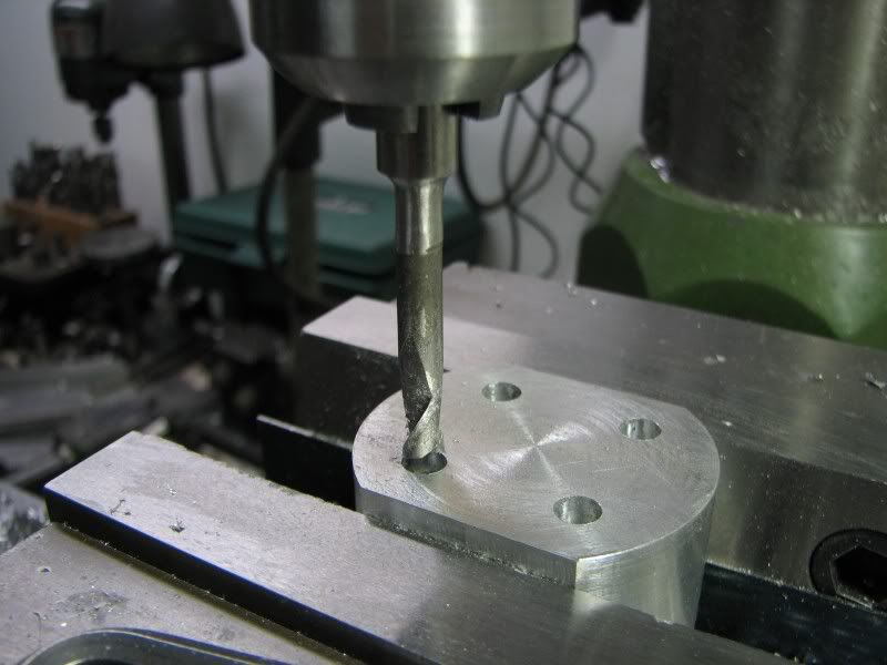
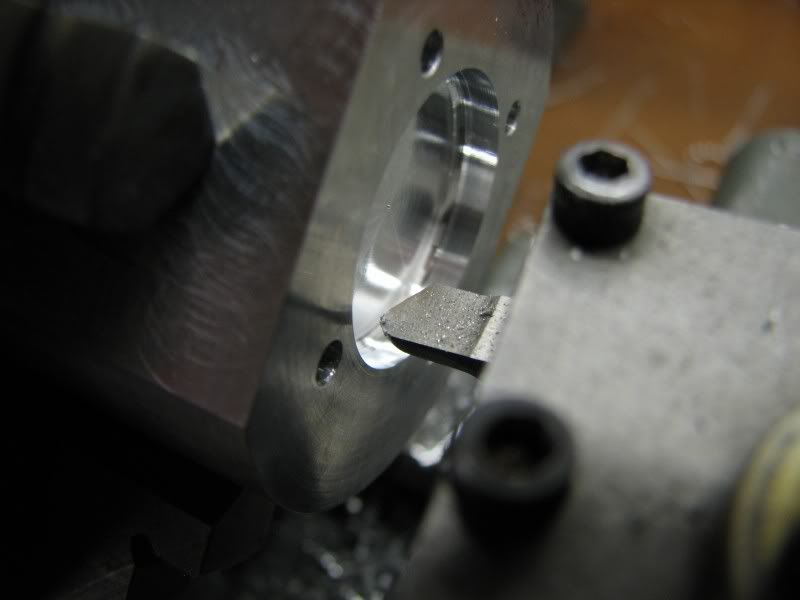
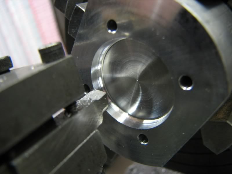
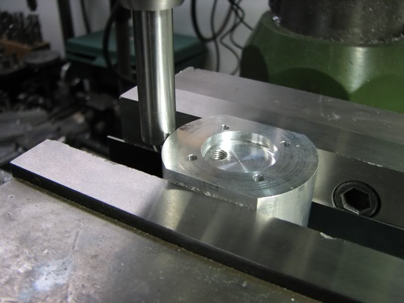
Hi Stew, the ignition system is not that bad, it's just the added expense of purchasing an electronic system. I do have one ignition system that I made years ago with a standard 12v. automotive coil and condenser in a box. The engine has a set of points and I plug a battery into it. It works fine but it has all the high amperage issues, point wear, battery size etc. Don't be afraid to tackle an IC engine, maybe just a hit and miss style, they're great to have running.
George
 
I second the thoughts on the posting of cyl. machining. I have not turned individual cyls yet and it would be most welcome.


Ron
 
It's all brilliant George, really impressive stuff!

How does this compare to other projects you have built? Is this your largest / most taxing?

Nick
 
Wow that looks like it should be up front of a Morgan three wheeler! Superb.


This man is without doubt a genius. This is the greatest work I have seen in 21 years of engineering.
 
:eek: amazing work George .......thankzz for sharing :eek: :bow: :bow: :bow:
 
I'm in the process of cleaning up all the little jobs to get the bottom end finished. I plugged the holes that I drilled for the oil galleries, I made all the bushings and pressed them into the crankcase and outer cover and I broached the keyways in the gears. I made up a broaching tool from a piece of 3/8ths drill rod. I milled it down to .062x.25 wide. I then filed some top relief on it, a couple of degrees, just enough so it wouldn't drag in the slot. I then hardened it and stoned the edges sharp.
HG.jpg


I then mounted the bar in one of my holders with the v-notch in the bottom. I adjusted the tool holder until I had the top cutting edge .03 above center and parallel with the ways. I had layed out the slot location on the gears so I could get as close as possible with the broach. I then started taking .005 cuts by cranking the carriage back and forth.
HF.jpg


In this picture you can see the finished slot. Sure beats the heck out of filing. I get enough of that anyway!
HH.jpg

 
Here's a picture of the gear train, minus the drive gear for the oil pump. I left it and the outer cover off so you could see the internals of the pump. I used a small round burr to put the dimples in the gear and used my 1/16th stamps to identify the front and rear cam. I never gave the orientation any thought when stamping the gears so F on my front gear is upside down. Oh well!
George
HJ.jpg
 
Thanks for the shot of the timing works, George.
Are the oil pump gears/pinions a standard pitch?

Dean
 
Never ceases to amaze me gentlemen.....George you are are Master in the truest sense of the word....

:bow:

Dave
 
Dean, all of the gears are 32 DP. It's curious that when I looked in the tool catalog for gear cutters they only went down to 12 teeth but the supplier that I buy from, https://sdp-si.com/eStore/ sells them down to 8 teeth. The reason that I went with 32 DP. gears in the gear train is because I thought I would have a better chance at picking up the center line of the teeth to put the keyways in. With a finer pitch like 48 DP if I was just a little bit off then my cam timing could be 3-4 degrees out.
George
 
I guess I should have said the supplier that I buy gears from has gears down to 8 teeth but the tool supplier only sells cutters that go to 12 teeth. Sorry for the confusion.
gbritnell
 
George,
Thanks for the link to SDP/SI. It's funny they are here on Long Island and not far! I had forgoten all about them.

Tony
 
George, thanks for explanation on your choice of 32 vs 48 pitch gears. Makes perfect sense to me!

The gear pump gears kind of had me fooled. Once pinion sized gears get so small, the flank starts to look kind of odd. Like the teeth on a small clock pinion, they get sort of a "club" profile.

Dean
 
George your works in metals can not qualify as even good machining.

Artistic sculpting would better suit the results!

If they were castings, cleaned up in the critical areas to fit the engine, it would
be very impressive. Watching it come together from flat stock is amazing.

Drop dead beautiful work!

Rick


Gentlemen, I know it's been awhile but I have been working on the engine. I pressed the crank back apart, put the rods on it, trued it up, (now within .0005 runout) and put it back into the crankcases to make sure everything fit. I have the lifters made, the various small screws made and the crank key made from steel. After assembling the rods and reinstalling the crank I found that I didn't have enough clearance at the top of the crankcase to allow the rods to clear properly so some surgery with the Dremel was required. After getting everything where is should be I changed the drawings to eliminate that problem in the future. I was going to start on the cylinders next but the motor on my Logan decided to act up so it's in the shop getting looked at. I wanted to keep moving so I started on the heads. There's going to be a lot of work on these things. I started out with two pieces of 7075 aluminum. I cut the flats where the intake and exhaust manifolds will bolt and then drilled and counterbored for the head bolts. (5-40)
HK.jpg

HL.jpg

HM.jpg

HN.jpg

HO.jpg


I then mounted the blanks in the four jaw chuck in my small lathe and counterbored and put the corner radius in.
HP.jpg

HQ.jpg
 
The blocks had to go back into the mill to do the spark plug holes and clearance counterbores. Nothing out of the ordinary, just drilling and c'boring. With that operation out of the way it was time to step out the combustion chambers. As is my normal habit I made up a step of chart to put the angle into the roof of the combustion chambers. I also had to make a companion chart because as I was stepping up the bottom angle I would be working around the radius of the chamber. I set up the piece, found the center with my edge finder, zeroed out the digitals and starting stepping. I was using a .125 ball mill to match the corner radius from the previous machining.
HS.jpg

HT.jpg


With the stepping finished I had to tilt the blanks to the spark plug hole angle to remove stock from the chamber side surface.
HU.jpg


Back
Top