90 degree V-twin engine

Home Model Engine Machinist Forum

Help Support Home Model Engine Machinist Forum:

This site may earn a commission from merchant affiliate links, including eBay, Amazon, and others.
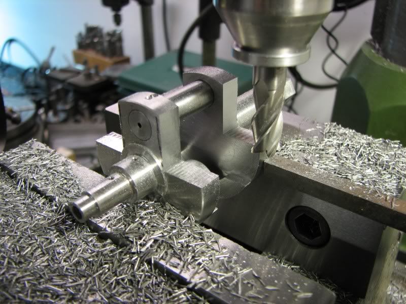
It's great watching your setups, George. I get a good feeling when I see that I do things in a similar way to your methods. Like I'm doing something well and proper.

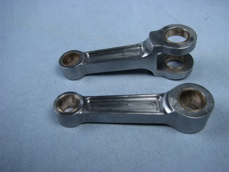
The rods look really good. Thanks for the photo essay!

Dean


Now that is Craftmanship!!! Thm: Thm: Thm: Thm:

Another post to be converted to .pdf for my growing reference files.

Ron
 
It's just so great to be able to watch this kind of work in progress.
Thanks George.
 
I've been quietly following along on this build...
Quiet because I'm dumb-struck by the brilliant work you're doing here George.

Very well done and documented; thank you for sharing with us!

Kind regards, Arnold
 
Brilliant George, I'd be more than happy with your roughed out rods as finished items!


Nick
 
First I want to thank everyone for following this thread and replying. It sure makes the extra time photographing and loading the pictures worthwhile.
Ok, the rods are finished. I cleaned them up this morning, made the bronze inserts and pressed them in. I took two finish shots and then thought I would take one more to show a size comparison to the Canadian penny. I used it for all the Canadian followers this time.
George
FY.jpg

FZ.jpg

GA.jpg
 
Beautiful George! You never cease to amaze me.

You have more work in two of those connecting rods, than I have in any one of my complete builds. Wish I had the amount of patients and skill you exhibit..

Just Super!

-MB
 
I don't even know what to say, unbelievable! Being a motorcycle fanatic I thought this would be a good project but I didn't expect all of this. You are doing some great work!
Dean D.
 
Another "wow" moment. Getting my mind blown every time I check your build.
The skill with machine tools is certainly worth watching, for anyone, but it's what you do after the lathe/mill stops turning that puts the filling in the Twinkie. Finish work is just something you really have to work at. All the final touches you put on parts that will never be seen. Inspiring.

Mighty fine, George. Mighty fine.

Dean
 
i and the rest of Canada thank you for taking the time to post pictures of your build


Great engine. :bow:
 
every time that I come here your work astonishes me george
really great :bow: :bow: :bow:

note to myself: next time that I have to make something, think 'how gbritnel would make it?'
note2: to make a rod use a fixture, use a fixture, use a fixture, don't hold it by hand!

 
Those are very nice looking rods. Were your finishing techniques, tools, and materials the about same as you used for your aluminum parts? Do you ever use Cratex abrasives for smoothing and buffing?

Regards,

Chuck

 
Wonderful build George. Thanks for taking the time to photograph and post the detailed setups for us. John
 
Hi Chuck, yes I use about the same techniques for finishing most materials. The only difference being how polished of a finish I want. I have used Cratex but for finishing I don't like to use too many spinning abrasives as they can put irregularities into the surface. By that I mean just enough surface finish so when the light hits it it looks like it's wavy. Kind of hard to explain. The biggest part of hand finishing when you're trying to make something look like a casting is filing. I have quite a few good jewelers files and a small selection of rifflers. I'd like to have more rifflers but they're about $16.00 apiece so I only buy one every once in awhile.
George
 
Saw your post George and my first thought was 'what a fantastic finish'...'he does great finishes'.

Then I read everyone's replies and see that I'm not the only one.

Amazing work. Always gives me something to work towards.
 
With the rods finished I started on the crankshaft. The crankdiscs were turned from 1144 stressproof steel. For this application almost any steel would do as there is not much that could warp but I didn't have anything large enough in my stock bin so when I ordered material I got the 1144. For those who haven't worked with it before it is a very machinable material and for one piece crankshafts it has the added benefit of no warpage like CRS. I don't have any pictures of the turning operations as they were straightforward. With both pieces turned, cutoff and faced to length I started doing the operations that would be more difficult after it was pressed together. First was to drill the oil passage from the outside edge to the center of the crank. Having to go through the throw hole I turned up a plug and clamped it in place to guide the .062 drill through it. After that I moved to the key slot for the crank timing gear. It is also .062 wide.
GB.jpg

GC.jpg


Here's a shot of the disc.
GD.jpg


The next step was to put the hex, for the starter, on the end of the other crankdisc.
I set the dividing head back up on the mill, indicated it square again, and cut the hex.
GE.jpg


The pieces went back into the lathe to reduce the size of the crank web. I did it in this progression because I wanted to leave as much stock on the discs for the other operations. After the lathe work they went back to the mill to cut the extra material out leaving just the counterweights. I originally designed the crank to have the extra material cut away from the sides of the throw webs and my friend said, " why don't you leave the discs round like a motorcycle crank?" I made up a test throw shaft and hung the rods from it to check the balance of the crank. I found that by leaving the discs round I wouldn't have enough counterweight to balance the crank so I will remove the extra material as I had originally planned.
GF.jpg

GH.jpg


Here is a picture of the assembled crank. The throw shaft is .375 drill rod which is actually .3755 diameter. When I put the throw holes in I reamed them .374 allowing for a .0015 press fit. The timing side disc will be pinned to the throw shaft using the already drilled oil passage. This will lock that side and also plug the oil hole. The flywheel side will need to be removable for servicing the rods so It will only rely on the press fit. The reason for assembling the crank at this point without the rods installed was to see if it could be trued up. Although I took extra care indicating everything when reaming the throw holes I wanted to check everything out before progressing. I pressed the throw shaft into the gear side and then lightly pressed the flywheel side on. I then put the assembly into my vise and squeezed it square. It was then pressed together the rest of the way. I then mounted the crank between centers to check the runout. I had about .005 which I didn't think was too bad for just squeezing them together for squareness. I then mounted the long shaft on the crank side in my lathe collet and set the indicator on the other shaft. With a small layout jack I pressed the crank up a few thousands at a time all the while rechecking the concentricity. Eventually I got it to within .0006 so I was quite sure at that point that down the road when I had to take it apart and put it back together I could achieve a pretty close runout dimension. The next step will be to cut the material from the sides of the webs.
GK.jpg

GL.jpg

GJ.jpg


th_confused0052 th_confused0052 th_confused0052 th_confused0052 th_confused0052

speechless......
 
New Years day! It's kind of quite around here today. My wife and I went to a friend of my son's for a party last night. We're all motorcyclists so we had a good time eating and telling lies. I don't drink much anymore, just a little bit of wine now and then but my wife had a good time so that's mainly why it's quiet. I went to the shop fairly early but a friend stopped by with some Mercedes hub caps that he want's masked and he had a Bridgeport mill on his trailer which I had to go look at. I finally got started about 11:00 am.
I made a spacer to fit between the crank webs so I could clamp it in the vise. I had to get the crank pin square with the mainshaft so it took a little bit of bumping and rotating to get it where it needed to be. I then started thinning the webs down.
GM.jpg


When I got them to the proper thickness I took an endmill with a small radius on the corner and cut the final depth. The next step was to go back and drill the oil hole/pin hole through the throw shaft. At the same time I drilled the oil holes that will lubricate the rods.
GN.jpg


The final operation for today was to cut a radius on the corners. I got them close to where I wanted them and will file the rest later. The crank won't stay like it is. I will hang the rods and pistons from the crank pin and slowly remove the stock from the counterbalancer until I get it close to balanced. I also have to plug the open oil hole in the end of the crank pin.
George
GO.jpg

GP.jpg
 
Back
Top