3 BALL GOVERNOR

Home Model Engine Machinist Forum

Help Support Home Model Engine Machinist Forum:

This site may earn a commission from merchant affiliate links, including eBay, Amazon, and others.
Brian
Glad to see you working on this project. The governor on the Victorian Engine gave up the ghost by self destructing the "lower" pivot points. I always wondered if I'd made them a wee bit too thin....(grin). Something quite similar to your design is going to replace it, so it's nice to have you plowing the ground ahead of time.

Seems once I installed the new vapor foam carb, the engine was no longer fighting a mixture problem and will now literally run away once it's warmed up. It produced enough force to crack the hinge points. Luckily the expansion arms held or things might have gotten a little exciting.

Now... I need ya to speed things up a bit, as the engine is due to be at a show in about 3 weeks....(grin). Nice work!!

Steve
 
See posts number 16 and 17 in this thread for the details of the upper and lower 3 ball governor arms.
http://www.homemodelenginemachinist.com/index.php?topic=3559.0

The drawings of the top and bottom 3 ball yoke have changed from what was shown in the old thread. Reason being, that when I went to machine them using the original drawings shown in the old thread, I realized that I had designed something that would be difficult to build. Not wrong, but difficult to machine. (I never built the 3 ball version---only the two ball.)

Everything else stays the same as the details of the 2 ball governor which are in the download.---Brian
 
Tonight I made a start on the upper arms for the 3 ball governor. I am using a peice of cold rolled 5/16" diameter, because thats what I had. First step was to turn down the ends to 1/8" diameter and thread them to #5-40 unc with a die in my lathe. I purposely made the threads 1/2" long which is 3/16" longer than the .313 called for in the drawing. I did this because I like to use a file while the part is still in the lathe to put a bit of taper on the end of the turned section, so that the die will start easier. I will trim them to exact length in a later step. This is something that I have learned by making parts to "exact length" and then screwing up the first 1/8" of thread trying to get the die to start properly. I recently purchased a small 3 jaw chuck to mount on my rotary table during my gear cutting exercise, so now I'm hoping to use it when I put the flats on 4 sides of these round parts.
3BALLUPPERARMS-STEP1002.jpg

upperarm-3ball-1.jpg


upper arm-3 ball.jpg
 
Okay---I set the rotary table with the 3 jaw chuck up on the mill table and set the degree scale to "0" (I was using the top edge of one of the rotary table clamps as a "witness mark" to locate the "0" mark, because you can set "0" mark on the table anywhere in a 360 degree circle. Then I started feeding the 1/2" milling cutter down in 0.010" increments and set the table stops so I could "mill to the line" along the left to right axis. I also set the digital scale on my spindle to "0" when the cutter was just "kissing" the top of the steel, so that I would know when my total depth of cut was reached.---One side completed on the 1/8" square section.--And please don't warn me about holding a milling cutter in a chuck.--I am aware of all the inherent dangers.---If you want to be safe, then don't you do it.
machiningupper3ballarmstep2001.jpg
 
With the first cut completed, I rotated the rotary table 90 degress, locked the clamps, and machined the second side.
machiningupper3ballarmstep2002.jpg
 
And on to the fourth side---I was getting a bit concerned by now, because the cross section of the part being machined was growing steadily smaller and smaller as I progressed, and I was hoping it wouldn't bend from the forces applied to it by the milling cutter. It didn't. Fourth side finished.
machiningupper3ballarmstep2004.jpg
 
I reset the table stops, reset the digital travel indicator on my spindle feed to zero on the large diameter (again), and proceed on the first of the four larger surfaces.
machiningupper3ballarmstep2005.jpg
 
And finally to the fourth and final side. It went well!!! I have never used a rotary table like this before, so I was looking foreward to the experience. It sure as blazes beats trying to do a whole lot of set-ups in the milling vice.
machiningupper3ballarmstep2008.jpg
 
A final note---I know that there is a lot of "stick out" beyond the jaws of the chuck. If the part had been slightly larger in diameter, I would have set up the other peice of tooling that looks similar to a lathe tailstock and placed the pointed end of it in a c'bore in the end of the part to "steady it up" while milling. As it turned out, I got away without using it, which proves either that I didn't need it, or more likely that the Lord takes pity on fools and amateur machinists!!!
 
Kinda looks like Inky Dinky spider, doesn't it. I had design work to keep me busy this morning, but ran out of work at noon, so I spent the afternoon in my machine shop. I finished the other 2 upper arms (Love that rotary table!!!) and drilled and tapped three 5/8" diameter brass balls I had left over from my first governor a couple of years ago. (Minimum order of 5 at the time.) At least I have proven to myself that the drawing of the upper arms is correct. Next thing will be to machine 3 lower arms.
INKYDINKYSPIDER002.jpg

INKYDINKYSPIDER003.jpg
 
I know it is a bit late into this post, but as Brian has just drilled his balls (no sarcasm please), and it has already been mentioned at the beginning, but I will just mention that I drill ball bearings a fair amount.

I don't go to great troubles about heating and cooling. Just using a couple of firebricks as a makeshift hearth, gang 'em up and heat to cherry red (I have found bright orange under fluorescent light to be ideal), then put another firebrick over the top to allow to cool down a little slower, or you could drop them into very dry sand and let them cool for an hour.

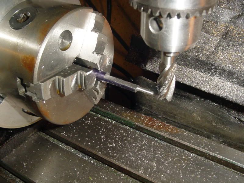
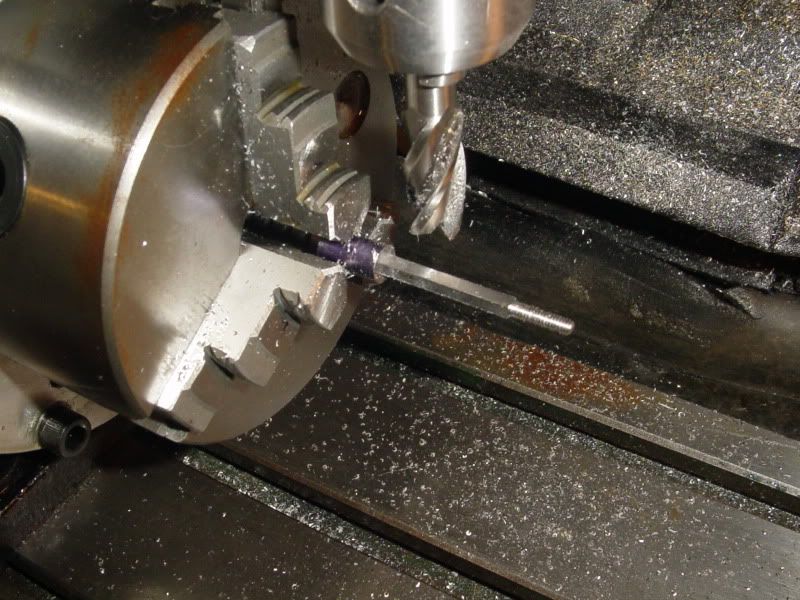
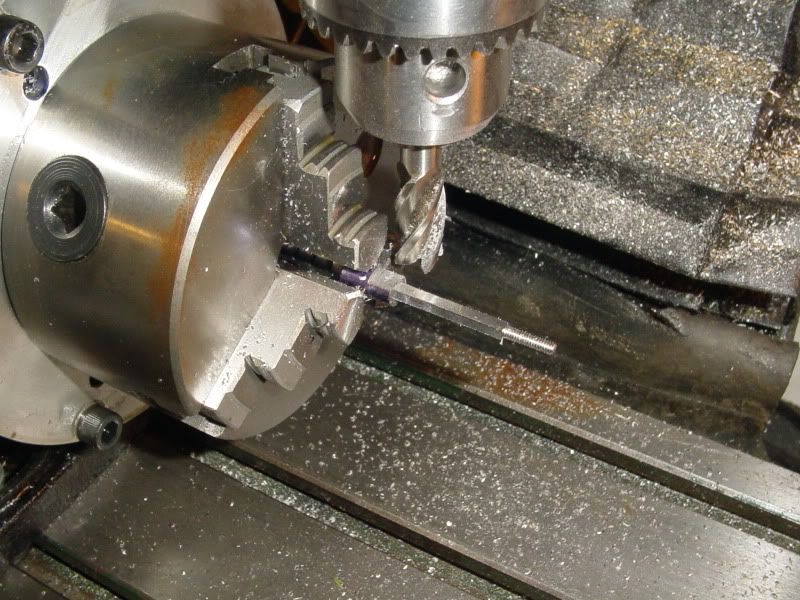
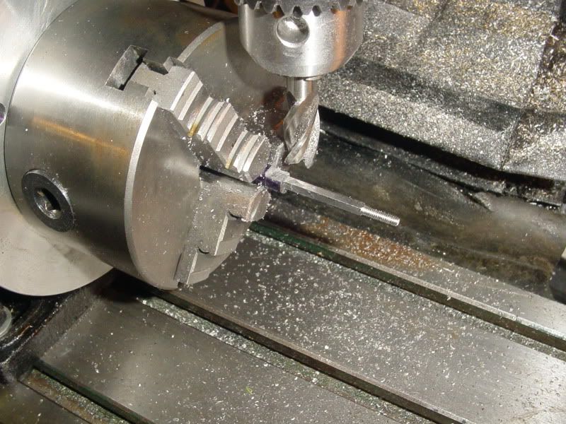
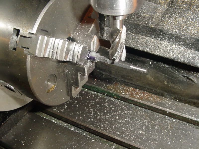
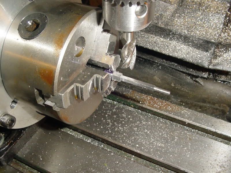
Yesterday, I processed 8 X ⅝" hardened steel ones, and drilled and tapped them 4 @ 4mm and 4 @ 4BA with no troubles at all, all to nearly full diameter depth. It is just like working with unhardened silver steel (drill rod), a bit tough, but do use plenty of high pressure tapping fluid for drilling and tapping (only use HSS tooling, NOT carbon steel).

The hard bit is today's job, removing the black scale off the balls to get them back to original lustre.

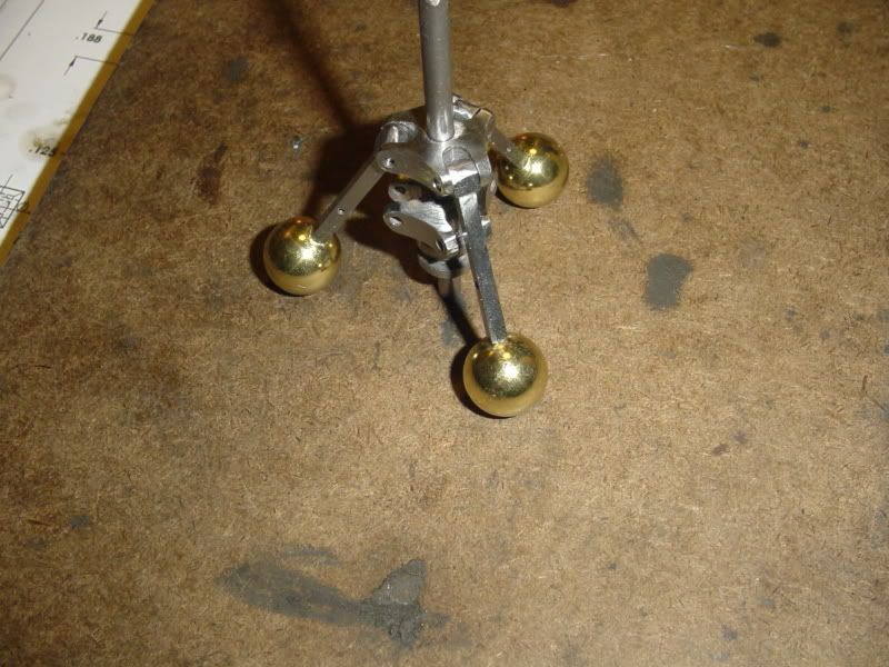
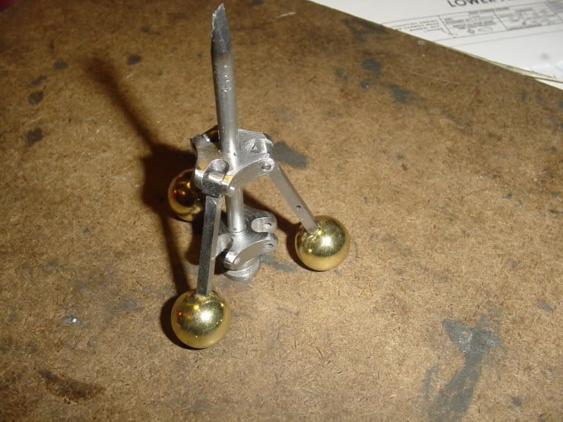
They work out very cheap if you buy say 50 in a pack, and to me, they look a little more realistic on a ball governor, but that is just me.

Sorry to interrupt this very good post.


Bogs
 
Thanks Bogs. Everything I have read prior to this argued against trying to drill bearings, Even after heating and annealing them. It said they were still too tough and would eat taps and desroy drills. I have fallen into the trap of "Heard it on the internet but didn't try it myself." Sorry about that. I stand corrected.----BRIAN
 
Thanks Marv---I like the shiny brass balls, but for someone on a tighter budget, or for those who prefer the grey steel look, they would be just the ticket.!!!----=Brian
 

Latest posts

Back
Top