3 BALL GOVERNOR

Home Model Engine Machinist Forum

Help Support Home Model Engine Machinist Forum:

This site may earn a commission from merchant affiliate links, including eBay, Amazon, and others.
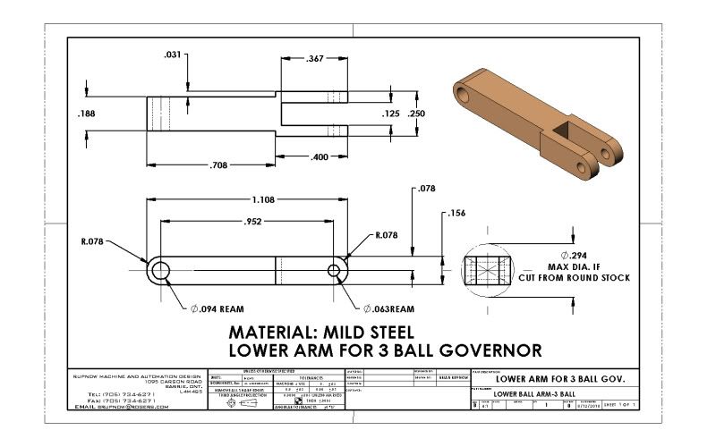
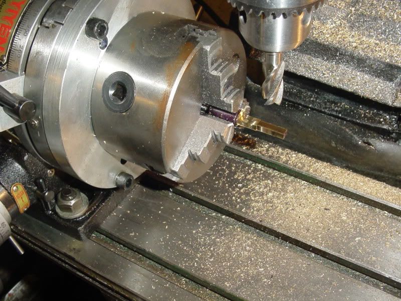
Here is the drawing of the lower arm for the 3 ball governor, reposted with no changes except for a couple of added reference dimensions. I can certify it as correct now, having actualy built the part from this drawing. And--I had to sneak in at least one shot of the rotary table set-up machining the arm from 3/8" brass round stock. Man, I don't know how I lived without that rotary table and chuck combination!!!
lowerballarm-3ball-1.jpg

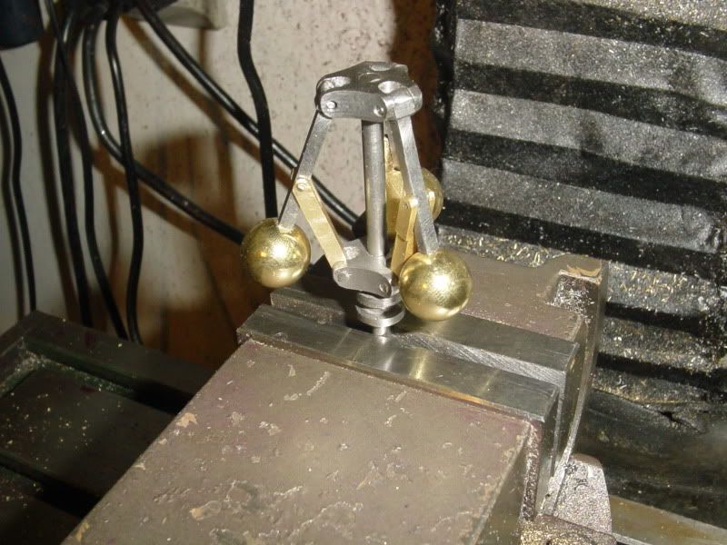
3-ballfinishedfornow001.jpg


View attachment LOWER BALL ARM-3 BALL.PDF
 
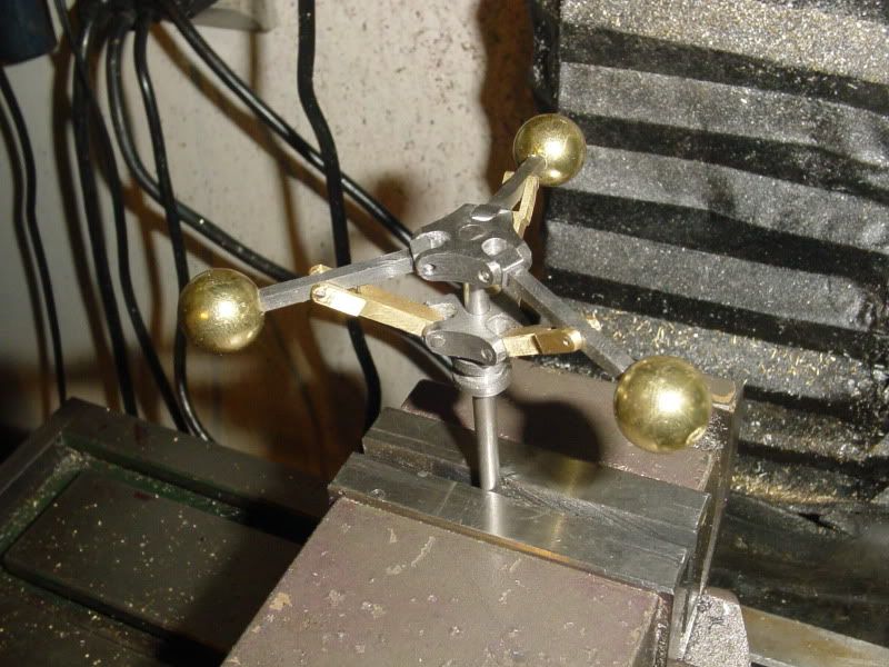
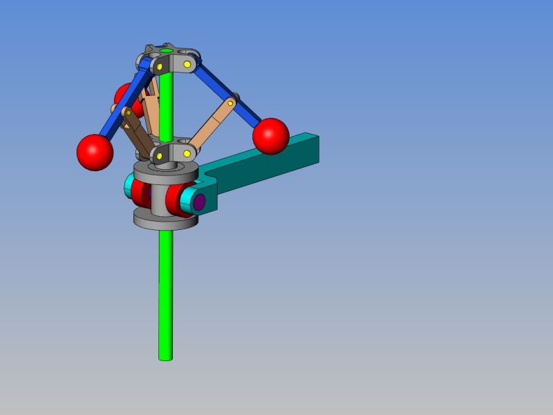
And here we have it all assembled on a tenporary stempost, in both raised and lowered positions. I don't plan on doing any more to this now. Someday in the future it is going to hold open the exhaust valve on an I.C. engine to create a hit and miss action. What did I prove here?---Well, nothing much, except that the drawings are correct, and the 3 ball governor can be built from the drawings. I hadn't machined anything for a while, and it filled in a couple of otherwise boring days.---Brian
3-ballfinishedfornow002.jpg

3-ballfinishedfornow003.jpg
 
radfordc said:
Dang...those things are still over 60C Rockwell hardness!

Seeing as how Brian has now finished with this post (unless more questions come along), this is what the heat treated bearings look like, after treating as I told you in my post.

Here are some softened ones in comparison to an original. Can you tell the difference?

softbearing1.jpg


And here they are after drilling, tapping and polishing. The 4BA are finished, and I am part way thru the 4mm. They take about 10 minutes each to get back to lustre, first a brass wire brush on the buffing machine, followed by a hard sisal mop with heavy cutting soap (these first two remove the black scale), then a stitched mop with heavy cutting soap, and finally an unstitched mop with a very fine buffing compound.

softbearing2.jpg


I don't re-harden them, so they will never regain that super high lustre, but I think that these are acceptable.


Bogs


I forgot to mention, you do lose something like 0.002" off the overall diameter, as when you heat them up, the surface oxidises (the black scale) and when you remove the oxidation, they are smaller.
 
That looks real good Brian.
It's on my 'looks like fun to do' list.
I also appreciate the additional information in this thread about using ball bearings.

When you were milling the arms, would it have been advantageous to put a machinist jack or some other support under the arm for milling?
 
Zee---I'm not really sure. I'm "feeling my way along" with this whole machining business. I didn't notice any undue deflection in the parts while I was machining them, but on the steel parts I was only cutting 0.010 at a time with the side of the end mill. I was feeding the end mill parallel to the long axis of the part, not crossways.On the brass arms, I got really bold and cut a full 0.090 depth and it didn't seem to want to deflect. I think the proper way would have been to support the free end with the part I mentioned before that looks like the tailstock from a lathe. However, these parts are just so darn small that I didn't bother. I'm not sure a machinists jack would have helped, because the force applied from the cutter wasn't down towards the table, but rather sideways as I fed the cutter along the length of the part.
 
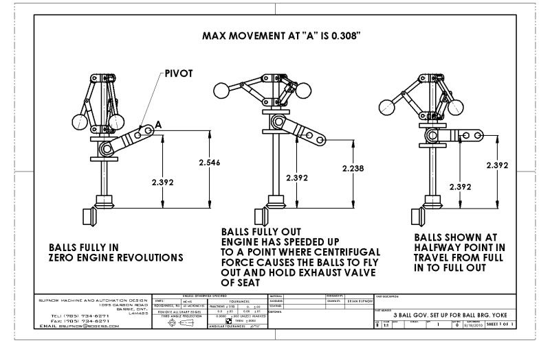
I've been doing a lot of thinking on how to marry the 3 ball governor to my Webster engine to make it a true hit and miss engine. In my previous expererience with the two ball governor, the pins in the lever fitted into a groove in the bottom yoke which was constantly revolving. It seemed to work just fine, but I can't help but think that there must have been a lot of wear on these stationary pins. I expect to see a lot more friction when the governor is used on an internal combustion engine. To eliminate the wear on these engagement pins, I have made a much wider slot in the bottom flyball yoke, and put a pair of 6mm sealed ball bearings on the lever. Ultimately, I am looking at putting an external adjustment on the governor which will let me vary the load on the governor compression spring thus changing the engine speed while the governor is running. Of course, this will have a 'feed-back" effect thru the lever and the bearings, so they have to be more durable and more anti-friction than the two ball governor which I used on the steam engine a couple of years ago.
3BALLGOVSETUPFORBALLBRGYOKE.jpg
 
That should work Brian, as long as the governor can overcome the spring tension on the exhaust valve. An easier way might simply be to make the pivoted arm short out the spark plug.
 
Tel--trouble with shorting out the sparkplug is that the valves still function and you end up "deadheading" a compression load in the cylinder, which would really cut down on the coast time.
 
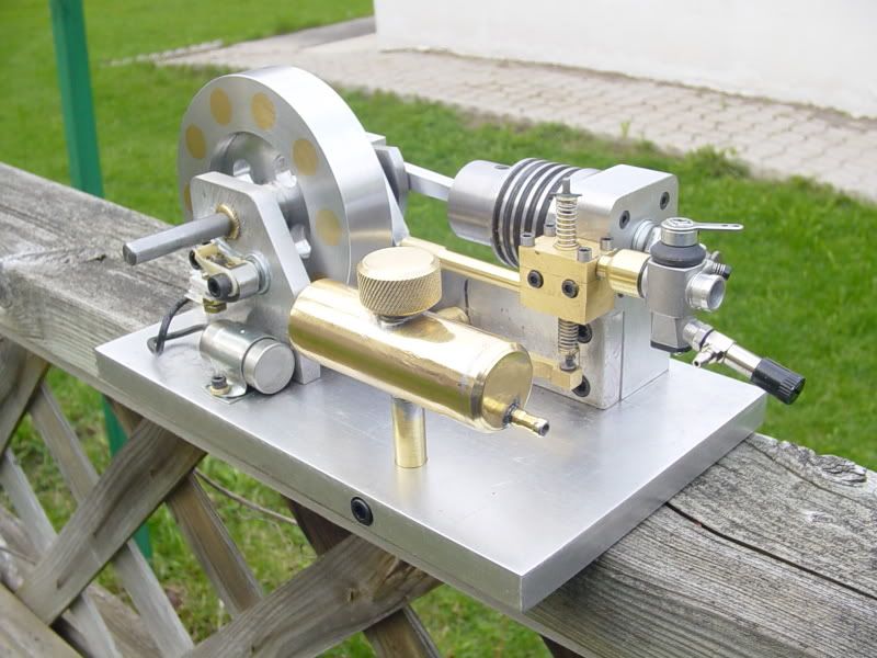
Take a good look at the size of the exhaust valve spring on this engine. A good size bumblebee landing on it would hold the valve open.
gastankinstalled004-1.jpg
 
Good point, it was just a thought. Looks like it should be fine.
 
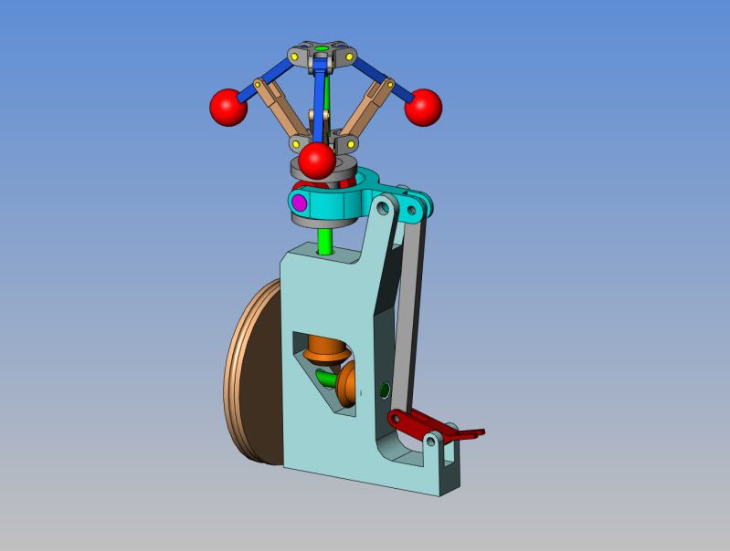
Here we have the govenor in its final form with all the required linkages. There is more information on it, but any further posts will be over in my thread about redesigning the Webster engine as a hit and miss. Those miter gears do actually mesh--Its just that I don't have the gears yet, and there is insufficient information in the gear catalogue for me to model them correctly.
3BALLGOVSHOWNWITHLINKAGE.jpg
 
Brian
Only one thing left to add to your design. You'll need a spring and adjuster collar to make it all work. Easy to do if you just place it all on the central shaft. The spinning balls won't collapse all by themselves, trust me....LOL

Steve
 
Steve--Thanks. Yes, I know that, but I haven't shown the spring yet. Springs are a rather nasty thing to model, and I'm still not 100% sure of all my finished sizes yet.
 
Back
Top