3 BALL GOVERNOR

Home Model Engine Machinist Forum

Help Support Home Model Engine Machinist Forum:

This site may earn a commission from merchant affiliate links, including eBay, Amazon, and others.

Brian Rupnow

Design Engineer
Project of the Month Winner
Joined
May 23, 2008
Messages
14,974
Reaction score
8,264
Location
Barrie, Ontario, Canada
In response to Crankshafters request----A few years ago I designed, built, and posted a thread about building a 2 ball governor. I am posting the link that will get you (hopefully) a download of it all in .pdf files.
http://www.mediafire.com/file/nw4ryqtqdu5/BRIANS FLYBALL GOVERNOR.zip
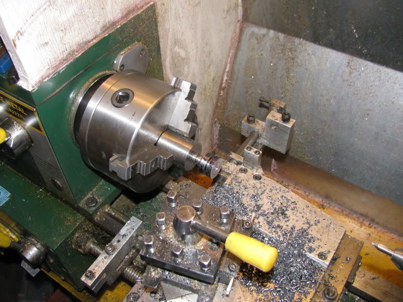
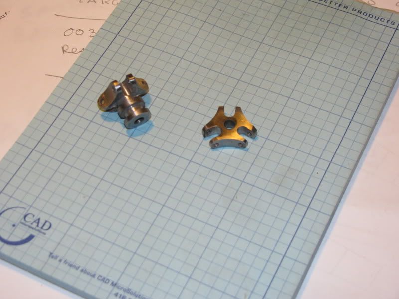
Someone later requested that I design a 3 ball version of it. I did, and they posted their finished project. I can't remember who it was now. I have never built it (the 3 ball version) myself. Only a few of the parts change. I am going to make one now, so I will post about it as I go.---Brian
BRIANSFLYBALLGOVERNOR-3BALLS-DRAWING.jpg


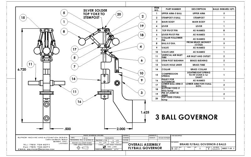
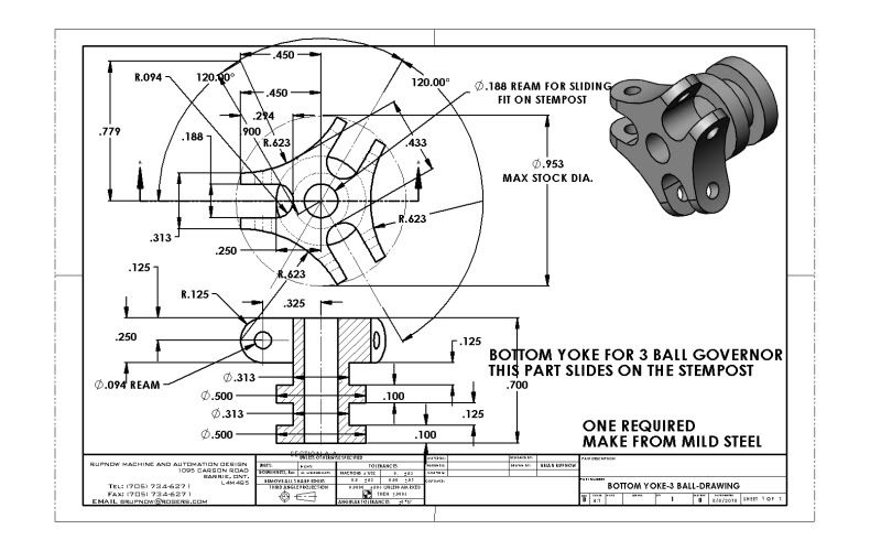
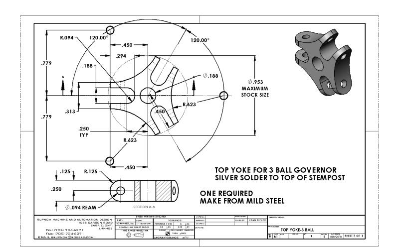
View attachment BRIANS FLYBALL GOVERNOR-3 BALLS-DRAWING.PDF
 
These are the parts I am working on today---The yoke with the round part on is used on the bottom, the one on top is different in that it doesn't have the round part on it . I am making two at one time here---I got a tad confused and started out thinking that the top and bottom yokes were identical.---They're not!!! I'm kinda making this up as I go along, machining wise, so I have turned all the diameters first, but left everything attached to the main peice of 1 1/4" round steel, to give myself something to hold onto when I take it over to the mill.

BOTTOMYOKE-3BALL-DRAWING.jpg

TOPYOKE-3BALL-DRAWING.jpg

3-ballyoke003.jpg


TOP YOKE-3 BALL-DRAWING.JPG


View attachment BOTTOM YOKE-3 BALL-DRAWING.PDF
 
and ill be watching evry move from over my mentors shoulder verry closely as i have just started with the 2 ball governor
just one question before i start with the school of hard knocks is it possible to drill and tap the ball bearings out of a large ballrace or are they too hard as i have a lot of those left from replacing the front bearings on my car the other week just thought id save them for this project
by the way i loved your last thread on the two ball governor especialy the video of it working
i cant wait to see this build and wish the best of luck
regards john
 
John---Don't even think about drilling and tapping a bearing ball. That way lies heartache. Buy some brass balls from McMaster Carr.
 
cheers fella i might just get some brass ones from the local gun shop he sells them in packs of 30 for £5 for use in catapult's atleast ill have a few to go at if i get it wrong
:big:
regards john
 
If you heat bearing balls to cherry red, keep there for some hours, and let cool slowly, they can be drilled just fine. I put my bearing balls to a tin can (ex-sardines), into the central heating oven (works with wood), and let them stay there overnight. Btw, it´s 00.30 hours atm, it´s 38C out- and inside my shop, so I won´t be doing that another time, for prolly some months. But I´ve got plenty of soft balls left...

I´ve drilled + tapped holes to lots of balls from bearings when I´ve made ball handles for various things. Here´s some I made to my lathe: the top slide (G. Thomas mod) and carriage locks. Though a bearing ball, the big one of the carriage lock (24 mm) never actually was in a bearing. But it was also glass hard. It got the same heat treatment, and afterwards was a joy to drill and tap, as were the rest. And many others ;)

Ballhandles.jpg
 
nice idea and method but i think ill try that another time might try and anneal some balls while ive got the wood fired furnace going with a shovel of coal it stays hot all night but i think ill settle for brass ones for me first attempt at this mate

brian i am pleased to announce that ive finaly made a viable pattern for the main frame of the 2 ball governor and it works in the kids sandpit all i need to do now is get it cast although ive done it 1/3 smaller than the drawings coz i stuffed up trying to convert the imperial measurements to metric :wall: im still going to carry on with it though as its me first time building a governor and i dont particularly wish to spend another 8 hours straight filing down another lump of maple floorboard
best regards john
 
I'm thinking as Brain either buy some or turn up some brass balls but to go through annealing process and drill a bearing ball seems like a lot of extra work.
But then I some times get some thing in my head and I just have to prove to myself I can do it myself. :big: :big:
 
Brian Rupnow said:
And how many did you drill and tap for 1/8" diameter threads????

Well, none. I don´t have 1/8" taps. But I did several for 3mm. In 8 and 15 mm balls. In the picture, they´re 15 mm balls, all have tapped 3mm holes, and two have 3mm screw stubs in them. And there are many more.
I just chucked them in a 3 jaw, started with a center drill, drilled and tapped. Put in a 3mm threaded stub, and (slightly) polished.
Even so, I think brass balls would look nicer in a governor. In a ball handle, steel balls might last longer without dents.

Balls.jpg
 
Timely thread. I've been thinking about a governor the last few days. No idea what I'll do with it...but I think they look cool. So I'll be watching.
 
just a thought if i had 3 balls flying round in appose to 2 woult the governor require a stronger return spring in respect of the extra weight under cantrafeugal force to get a little more concistancy from the action as its run at different speeds
 
John---The whole reason for using a governor is to maintain a constant speed. Not to "Run at different speeds". What that final speed is will be determined by the strength of the spring, the weight and quantity of balls, the speed the governor is driven at, and the length of the levers involved. My original 2 ball design only moved a small peice of 1/4" diameter rod with a steam port in it back and forth in a guide, so it didn't have to generate very much "power" to move that small peice of rod. This 3 ball unit may ultimately be used to hold an exhaust valve open on an I.C. engine, so I want it to be able to generate a bit more power.---Brian
 
I hope you fellows notice that the 3 drawings I have posted keep changing and evolving as I make the parts. They are now shown in their final form, and the parts are finished. As I mentioned in an earlier post, I got a little confused and thought that the top and bottom yokes were identical. Thinking this, I went ahead and roughed out two bottom yokes on the lathe. On closer examination, I found that the top and bottom yokes were different, ---The top yoke which gets soldered to the stempost didn't need any round part on it, so my second machining operation was to machine off the unneeded round part from one end.
3-BALLGOVPARTS009.jpg
 
I then cut off about 2 1/2" of the 1 1/4" shaft I started out with (still attached to the parts) and walked it over to the milling machine where I set it up vertically using one of my home made V-blocks in my milling vice. I drilled out the three 3/16" diameter holes at the end of the arm slots, and used a 3/16" two flute end mill to plunge cut and open the slots to the outside of the peice. I then set up my boring head set for a 0.9" radius and cut away the outside of the body in 3 places.
3-BALLGOVPARTS010.jpg

3-BALLGOVPARTS011.jpg

 
With that operation finished, I flipped the part onto its side and using another homemade V-block I drilled and reamed the six 3/32" diameter holes. I then put the part back in the lathe and turned the 1/8" radius on the ends of the arms. (If I did this again, I would have put the rads on before the milling operation, to avoid all the interupted cuts.)
3-BALLGOVPARTS003.jpg
 
I didn't take any pictures of drilling and reaming the part in my lathe for the 3/16" center hole, nor did I show cutting the outermost peice off with my bandsaw. I would have parted it off, but it was out quite far from the chuck jaws, and I didn't want a disaster at this stage of the game. I did part off the second peice which was still attached to the 1 1/4" diameter shaft.
The parts were then cleaned up a bit on my 1" belt sander, and Voila'---The upper and lower yokes are finished.
FINAL3BALL002.jpg
 
Terrific looking set of drawings Brian, and thank you for sharing with us. How was it you were able to index the slots and the large radius cutout between the arms?


BC1
Jim
 
bearcar1 said:
Terrific looking set of drawings Brian, and thank you for sharing with us. How was it you were able to index the slots and the large radius cutout between the arms?


BC1
Jim

Jim--I'm not exactly sure what you mean. My vice has a swivel base with a degree scale on it, and the 3 large outer radii are directly in line with the 3/16" slots. Of course, nothing is simple, and the center of rotation of the vice was offset quite a bit from the center of the darn part, so every time I swivelled the vice I had to "Find center" again on the part. Perhaps If I did it again I would use my rotary table with the 3 jaw chuck mounted on it. That way the centers would stay constant and save me a lot of time finding center between machining operations. Is that what you meant?---Brian
 
Oh yes, now I understand it, Duh! It never occurred to me that you were using a swivel vise. Gees. I agree with you about using a RT for this piece, yours turned out rather well I might add. It is going to be exciting to see the finished product in use on your engine. Thanks,

BC1
Jim
 
Back
Top