1:8 scale 3HP buffalo twin marine engine

Home Model Engine Machinist Forum

Help Support Home Model Engine Machinist Forum:

This site may earn a commission from merchant affiliate links, including eBay, Amazon, and others.

mikemott

Well-Known Member
Joined
Oct 24, 2014
Messages
53
Reaction score
67
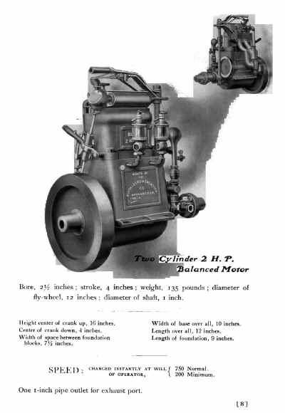
This is the engine that I propose to build the bore is .375 inch and the stroke is .5 inch.
I am in contact with the owner of the boat and engine, and am building the boat also in 1:8th scale, the boat is called Skipjack and is located in the Muskoka region of Canada


Once I get comfortable with how this board works I will be able to organize my posts clearly.

Michael

scan0006.jpg
 
Michael,
From reading your other posts and looking at your web site, you certainly have all the skills and and equipment necessary to do a successful build of the engine you propose.

If you have any photos or links to the prototype engine I, and others, would be interested in seeing them.

I have built a pile of engines in the 3/8 X 1/2 inch bore stroke configuration and have learned a few things about them. I am currently building a few more to power some more 45mm (Gauge 1) locomotives. If I can be of any assistance to you please ask.

Gail in NM

 
Hello Gail, thanks for the compliment. I am waiting for the owner to get me more information about his particular engine, in the meantime I have been gathering as much information as I can about the early small Buffalo engines, the website Old marine engine has by far the most information that I have been able to find.This link to the section on The Buffalo engines, is all I have at the moment.

I have begun making a concept drawing of the engine, it takes a bit of time to prep them to post because I have to change them from my old version of Autocad LT200 to another program that can save to PDF or Jpeg.
attachment.php


the drawing is full size the cap screws for the con rods are 1x72

Michael

View attachment engine.pdf
 
Michael,
Concept drawing looks good. Thanks.
For the benefit of other viewers here is a direct link to the Old Marine engine website, and the photo from it.
http://www.oldmarineengine.com/history/Buffalo/Buffalo.html

Buffalo%202HP%20Picture.html
2HP.jpg


Since you are new to HMEM you may not have seen the following threads. You might find them useful for design and construction ideas.

First is Kel's build of a 4 cylinder version of Tiny. It is overhead valve, as opposed ty your side valve, but is water cooled

http://www.homemodelenginemachinist.com/showthread.php?t=10240

Second is Bills Briggs & Stratton scale model, which is side valve.

http://www.homemodelenginemachinist.com/showthread.php?t=5343

I too run older versions of ACAD. For me the quickest way to generate JPG's and PDF is to plot them within ACAD and then scan them. I have a modern scanner that will output JPG or PDF quickly to a file that I can then publish. Has the advantage that I can also scribble notes on the plot with a pen that then show on the published item.

Gail in NM

 
Gail thanks for the tip regarding the pdf's and Jpegs I have done that but forgot. I will check out those other builds.
Michael
 
One of the issues that I am facing is the fact that the cylinder body and head appears to be one piece,. a couple of questions come to mind and I have been searching through the various sections looking for an answer but have not yet satisfied myself of the answers.
The first one is that it appears that the valves are inserted through the top of the cylinder then capped with some hex "bolts"
This also appears to be the same with the spark plug.

One thing I have considered is to basically build an inner core and an outer shell to form a cavity to accommodate the water cooling.
Does this sound like a good or doable idea?

Michael
 
Quite a common way to do things, make the outer casting and bore it out to take separate cylinder liners. You can open out the central part of teh bore to form a waterspace. Or fabricate a "box" on have holes top & bottom for the liners.

This launch engine build may give you some ideas

http://www.modelengines.info/naphtha/Main/
 
Jason Thank you for the link, I was smiling all the way through the pictures of the fabrication of the crankcase and cylinder case. I have been thinking about building the crankcase the same way.

michael
 
A little off topic, but...

PDFs can be created easily using PDF Creator. It installs as a printer driver and can produce a PDF from any program that prints. No need to scan it after printing it.

There is also a PDF Creator Plus but that is a for money program.
 
After some long sessions at the drawing board and reading through a lot of threads pertaining to the very small engines particularly the "Tiny" thread. I have drawn a slightly more developed plan of the 3 HP buffalo engine.
The general arrangement is obviously not complete yet, any feedback regarding my direction so far will certainly help me continue with the design.

These drawings show my thinking so far, normally I would be racing away cutting material but in this arena I am still climbing up the learning curve.

Michael

002 3HP sht 1 x 800.jpg


001 3hp sht 2 x 800 .jpg


003 3HP sht 3 x 800.jpg


View attachment Buffalo 3HP sheet 1.pdf

View attachment Buffalo 3HP sheet 2.pdf

View attachment buffalo 3HP sheet 3.pdf
 
This evening I did a bit of test machining of the top piece of the cylinder head. It still need some finishing as it is a bit rough yet.

The cavity on the top side will get a cover sweated on and the plug body will thread through the cover plate.
the 4-48 threaded holes will allow the valve rods to be inserted so they can be seated. after they are placed then the plugs can be threaded in.

The top piece will be sweated onto the lower part which will then form the whole cylinder assembly.

Michael

IMG_4670x800.jpg


IMG_4673x800.jpg


IMG_4676x800.jpg
 
Pressing on the last two days have been taken up machining more of the cylinder head.
I made a couple of support blocks to fit inside the lower section of the cylinder so that I could finish off the outer shell and ports. they are set up so that the 10-32 screws also screw into the spark plug threaded section of the top part.
attachment.php

attachment.php


attachment.php

attachment.php

Next some careful filing to bring the flats to the rounded shape of the water jacket.
attachment.php

attachment.php


After a lot of hand work the shape is getting closer to what I think looks like the original. The liner is just a test piece.
attachment.php

attachment.php

attachment.php

attachment.php


The valve stems are going to made from some robust sized sewing needles the diameter is .046
attachment.php

attachment.php


It is a bit of a surprise as to how long this small machining takes. The most challenging part was the inlet and outlet ports, because the amount of material is very limited.

Michael

IMG_4678x800.jpg


IMG_4683x800.jpg


IMG_4684x800.jpg


IMG_4688x800.jpg


IMG_4690x800.jpg


IMG_4692x800.jpg


IMG_4694x800.jpg
 
I am seeming to have difficulty adding the pictures inline without having a string of attachments at the end?

Michael
 
after removing the support plugs I noticed that I had in fact cut into the water jacket with the port drill.
IMG_4695x800_zpsb2bd8961.jpg

I decided that I could sweat in a plate to block the holes so machined up a sleeve then parted off two rings and cut them to fit into the water jacket space.


Also added the inlet for the water between the exhaust valves, that way there will always be fresh cold water at the hottest part of the cylinder head.


the holes for the cylinder liners still need to be reamed 13/32 and a plate made for the inspection hole in the jacket.


Michael
 
Herbie thank you.
After spending most of yesterday contemplating what I have done so far, I have made the decision to start over, I have worked on this concept model long enough now that the little changes that I kept making mainly to deal with the water jacket were not going to satisfy my mind.

In order to maintain the external appearance of the engine and to provide adequate water circulation, and to keep the wall thicknesses withing some reasonable limits I am changing the bore to .3125 bore with the same .5 inch stroke. and increasing the diameter of the valve heads to .156 changing a few of the assembly methods.
I am presently working on the new drawings and preparing the blank pieces of metal.

Michael
 
After a lot of long hours machining and then starting over, then starting over for a third time I am finally on track. I also decided that I needed to make the bolting flange integral to the rest so I will only need to add an oval plate with two holes for the bottom of the cylinder liners.

IMG_4713x800_zps1ebd0610.jpg


The holes through the side wall were bothering me too much, so started again, Disaster struck quickly because I datum-ed from the wrong side on the mill and machined a nice swath right down the side of the water jacket.


Pictured is the third cylinder under way and going pretty smoothly considering the previous starts.

I made a change to the bore to 5/16 kept the stroke the same, this will give me quite a bit more space for the water flow through the top of the engine.


Again the most time consuming part was the inlet and outlet ports, All my machines are manual, and I spent the better [part of yesterday fitting a 6 inch dial vernier to the fore and aft motion of the table, This made the set up so much easier than readjusting my 1/2 inch travel dial indicator.

Michael
 
Started to work on the new head part today, I also figured a simple way to use the mill to tap the spark plug holes without having to change the set up from drilling. I put a couple of 1/16th flats at right angles to each other close to the threads of the tap and slipped a 1/2 inch thick aluminum disk with a couple of set screws at right angles to the lower position and then used the drill chuck as the guide by finger tightening the tap in the chuck lowering it to the work and then just releasing it enough so that it slid out toward the work.


The tap is a 6 x.05mm it was the finest thread size in the range that I wanted for the spark plugs.

I also made a small .155 inch end mill with a .015 radius at the face so that I could cove the space in the combustion chamber a little. it is simple but works well enough at the small scale I am working with. I turned it up out of some drill rod then shaped it on the large diamond wheel grinder that was surplus from an opticians lab.


Made a test cut to check that it was going to work.


There is still a lot of hand work left to finish shaping but I am pleased with the progress.


Michael
 

Latest posts

Back
Top