
Kozo A3 in 1.5" scale
- Thread starter kvom
- Start date


I'll probably blow my mind first ;DJeff02 said:Man at this pace youre going to be blowing your safety before spring!
kvom said:No further progress foreseen here until after Christmas.

kvom said:Not wanting to experiment with a $75 casting that has a lot of work in it already
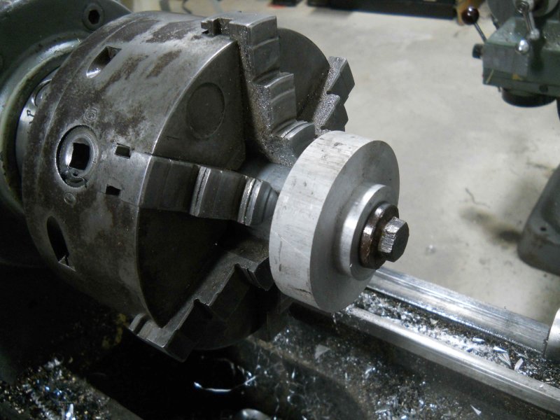
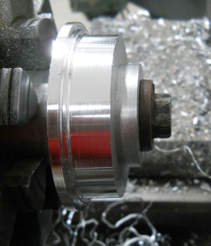
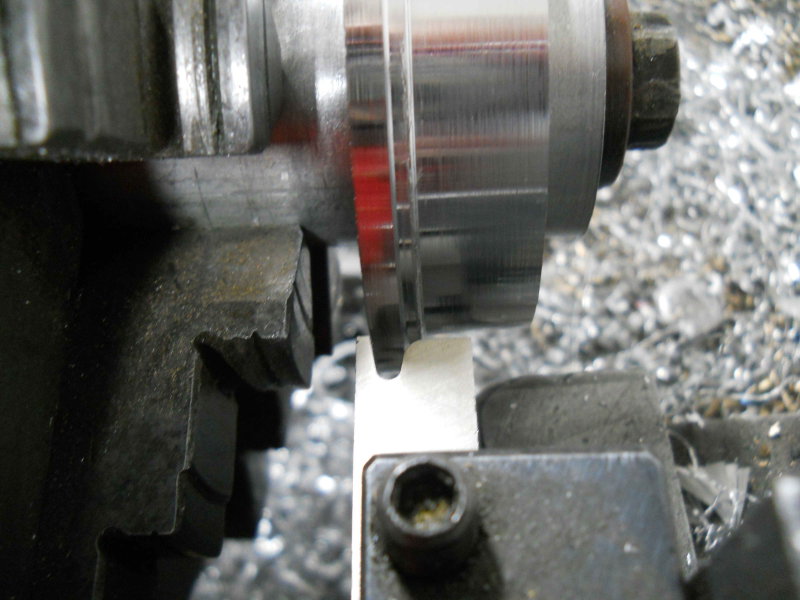
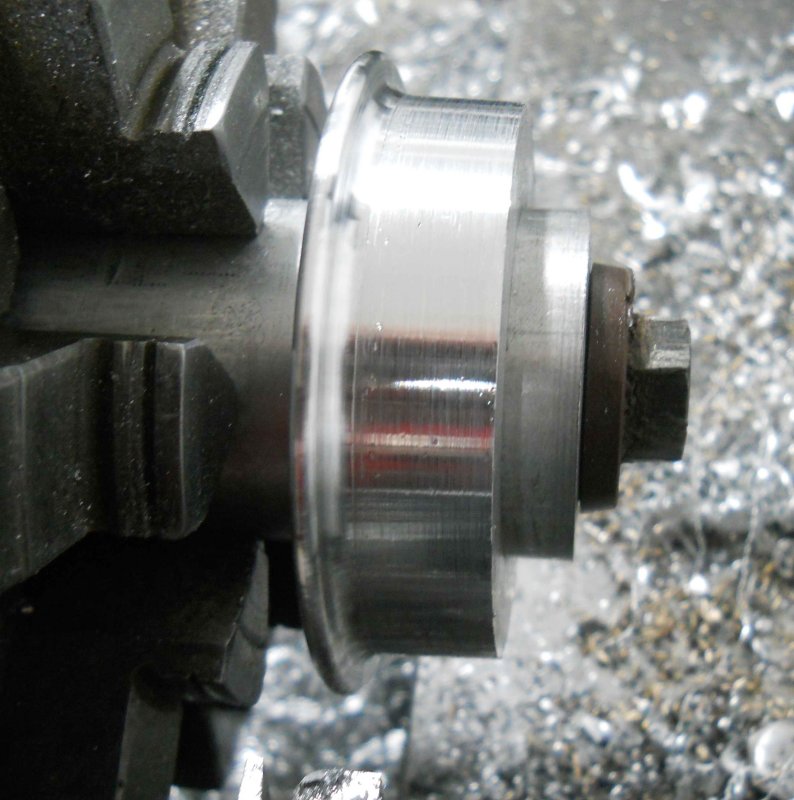
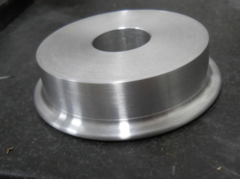
kvom said:This evening I started turning the flange and tread for the drivers. All went well until the flange profile tool grabbed and twisted the aluminum mandrel in the chuck jaws when finishing the 2nd wheel. :-[ So now it's all out of square, and I'll have to make a new one to finish the last 2 wheels. That can wait until tomorrow.
Enter your email address to join: