You are using an out of date browser. It may not display this or other websites correctly.
You should upgrade or use an alternative browser.
You should upgrade or use an alternative browser.
Vertical I.C. Rupnow Engine
- Thread starter Brian Rupnow
- Start date

Help Support Home Model Engine Machinist Forum:
This site may earn a commission from merchant affiliate
links, including eBay, Amazon, and others.
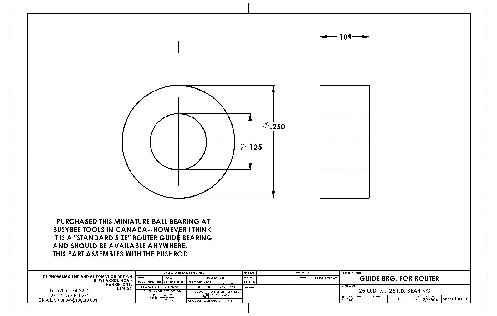
A word about the gears used in this engine.---I have a set of 24 dp gear cutters, and will be cutting a 30 tooth cam gear and a 15 tooth crankshaft gear. if you happen to have a set of 32 dp gear cutters, then a 40 tooth and a 20 tooth gear will give you the correct ratio and center to center distance of .9375" which is critical to maintain. For those of you who have "mod" gear cutters, can someone please check and see if there is a set with 2:1 ratio that have a center to center distance of .9375"(23.81mm)
Last edited:
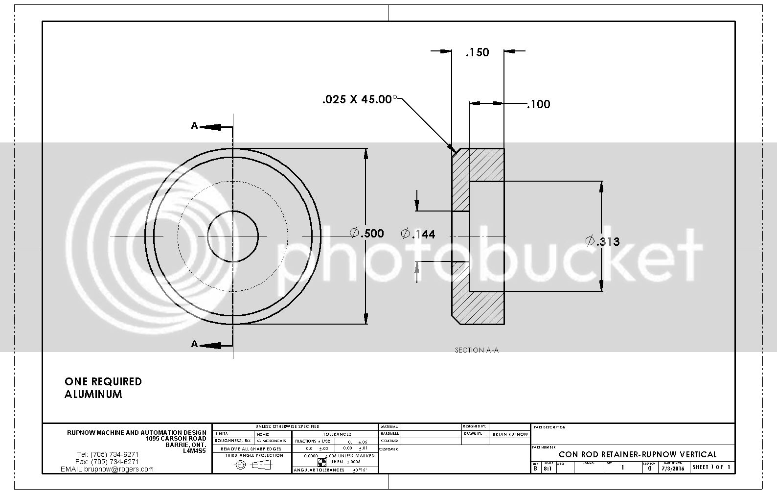
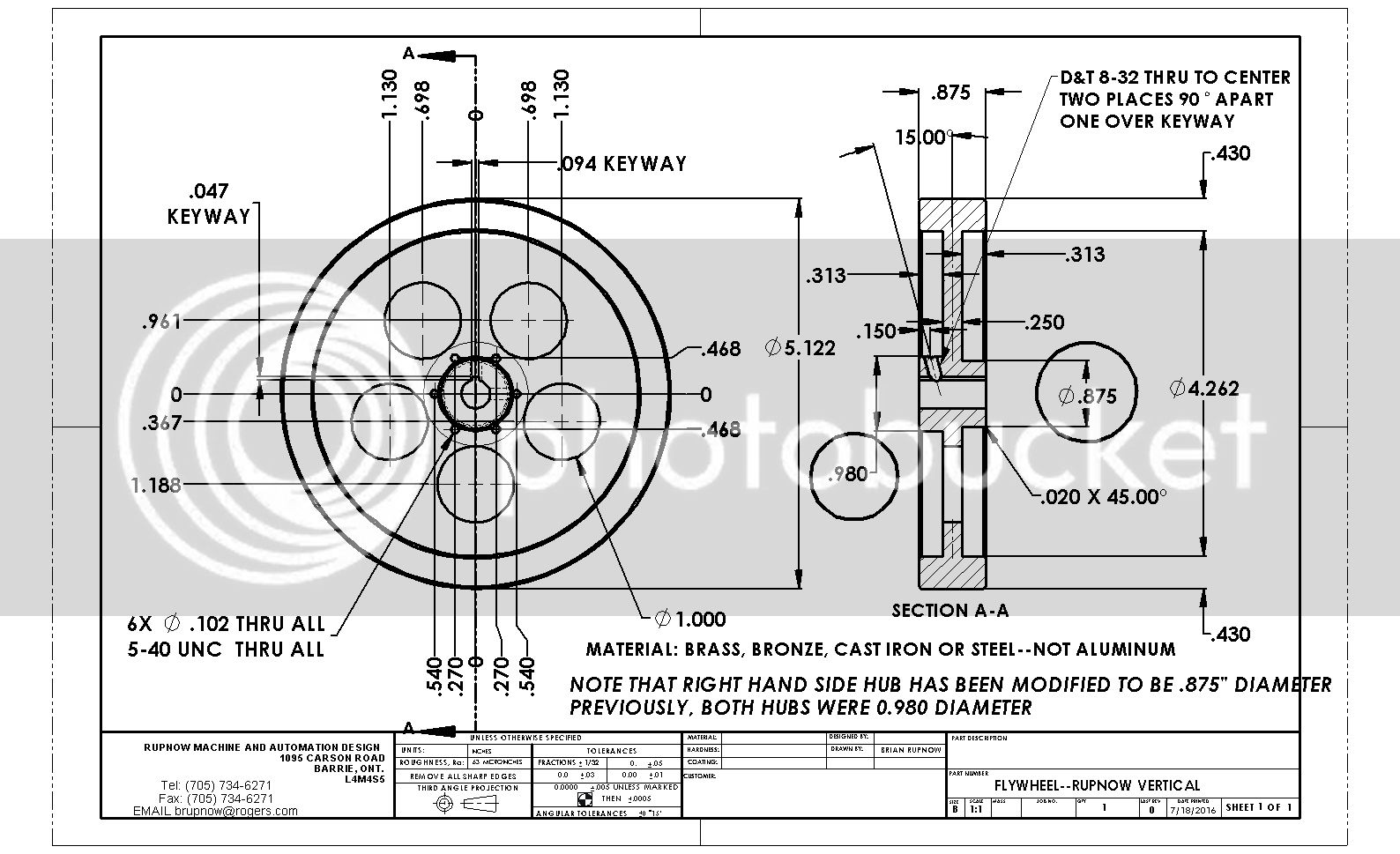
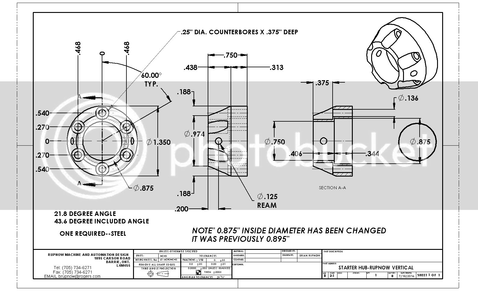
EDIT--EDIT--EDIT--I just discovered that the starter hub wasn't going to fit onto the flywheel, the way it was dimensioned. I have modified the flywheel drawing and the starter hub drawing to reflect these changes. Sorry if I screwed anybody up. The corrected drawing are going into the pdf files today.---Brian


Last edited:
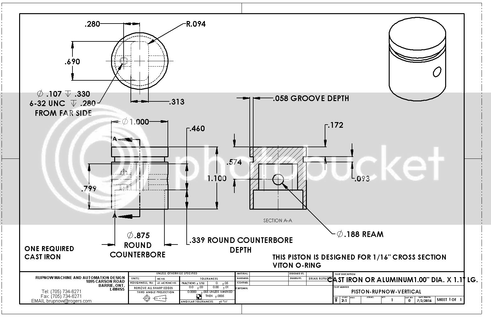
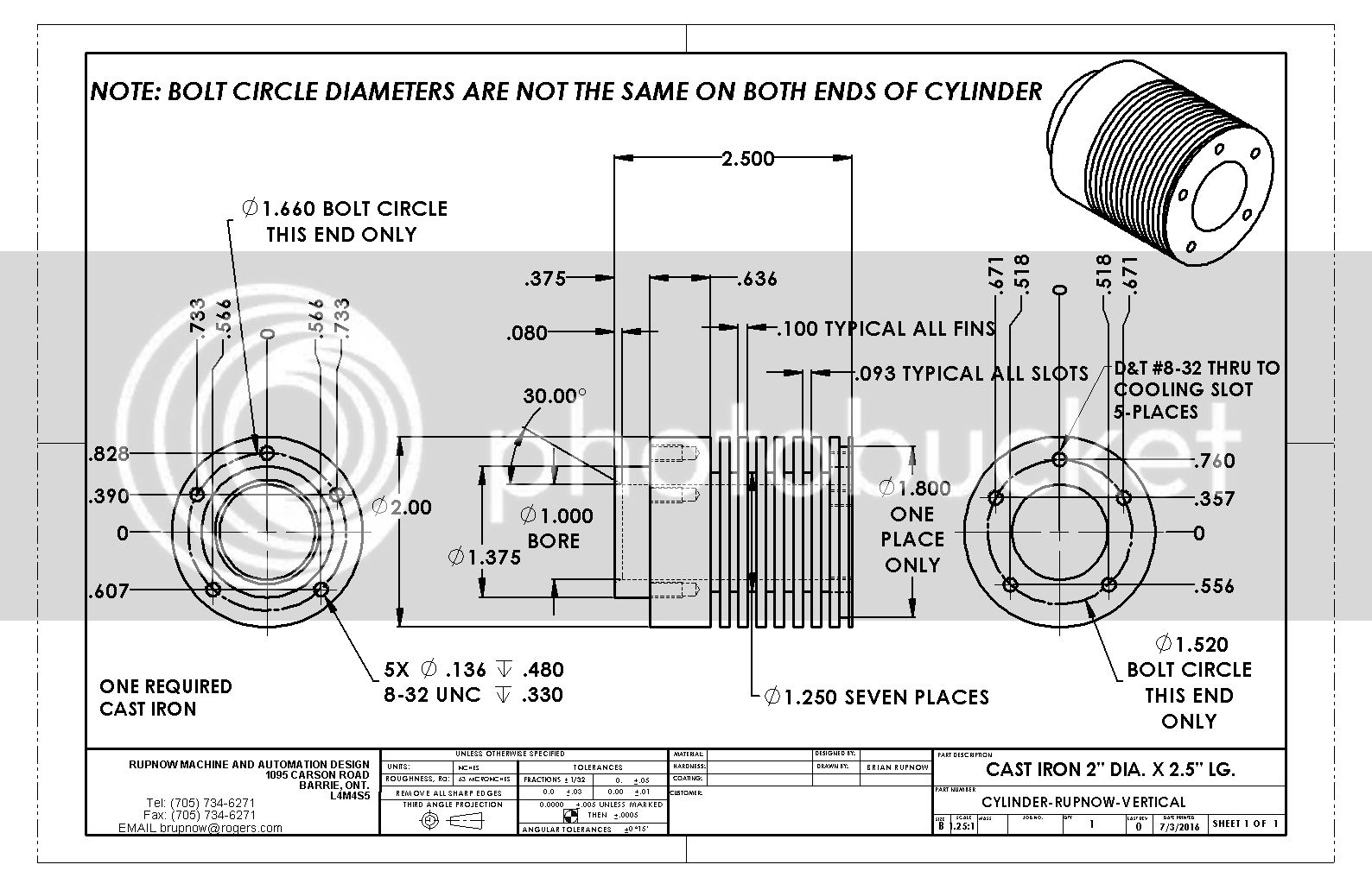
So---here are the two most complex parts on the whole engine. The cylinder is very straightforward. The cylinder head is more complex, and will require some careful thought before starting to "carve metal". At this stage of things, I'm only posting .jpg files, because some of the web-sites I post on don't have any way to post a .pdf file. If somebody really has a "Jones" to start building, email me at [email protected] and I will send you a .pdf file. I will make a complete set of pdf files after I have completely finished all of the design work. I am going to build this engine myself, but not until I have secured and modeled a set of Tecumseh points and figured out just how the ignition is going to go together. Regardless, the cylinder and cylinder head aren't going to change.



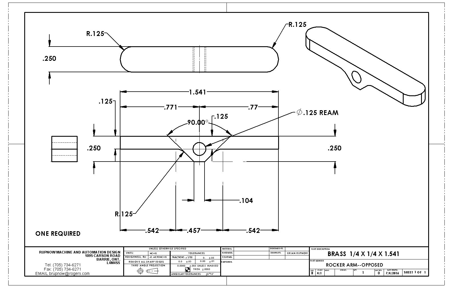
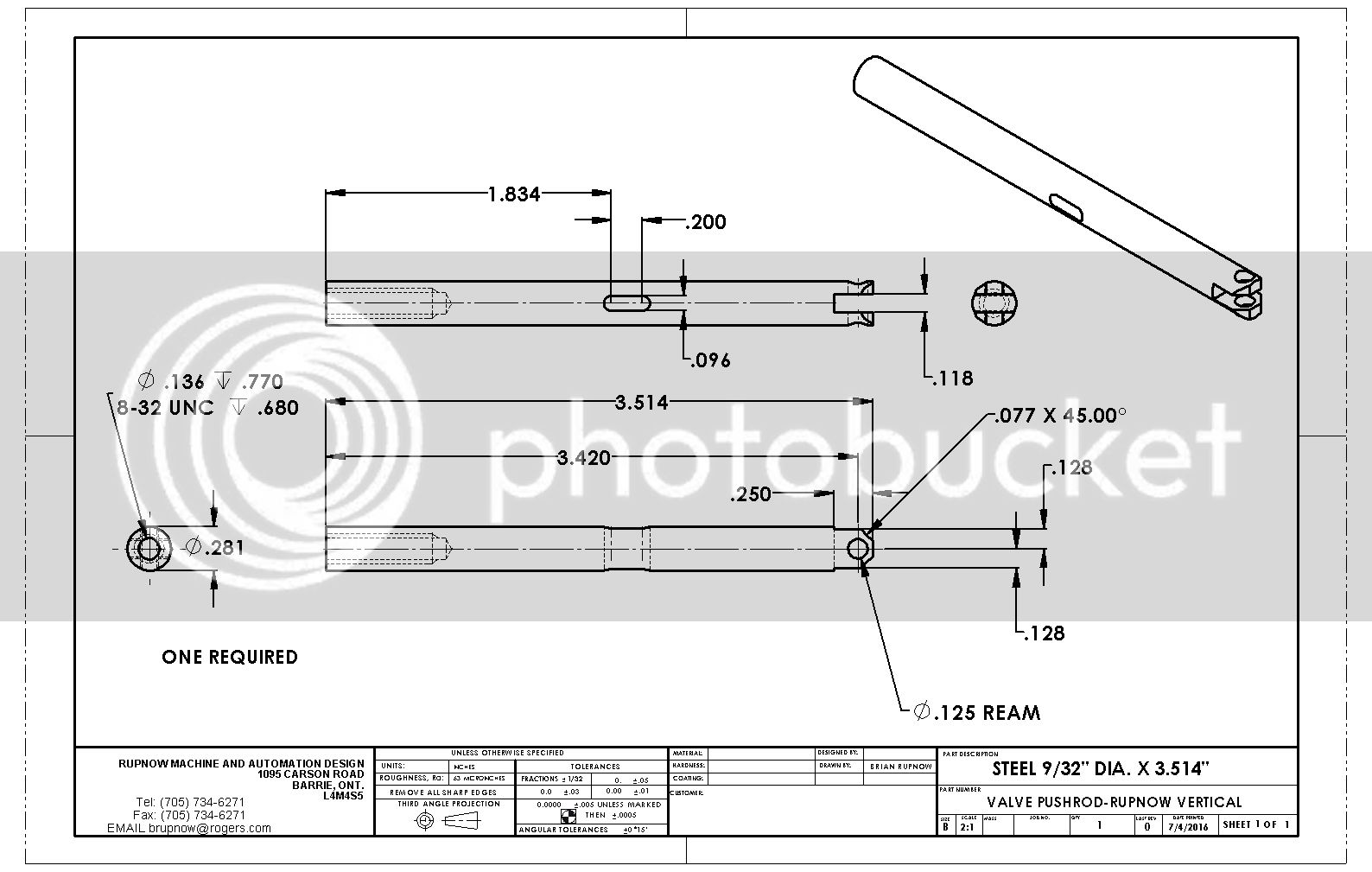
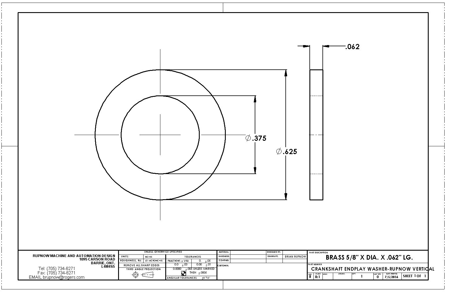
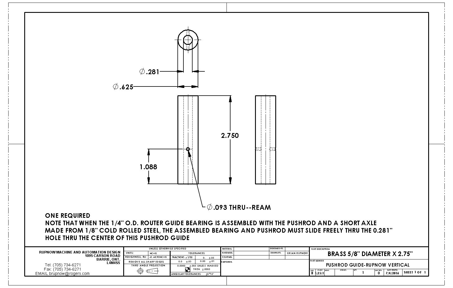
It's the end of Canada day long weekend. I didn't work on this all weekend--honest.--But I did start it Friday morning. It's amazing how much stuff actually can be designed/modelled/detailed that isn't affected by the ignition points question. Here we have the valve, with friends.
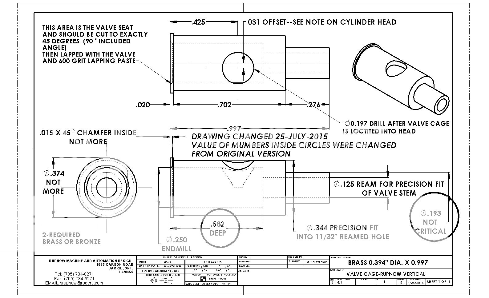 http://i307.photobucket.com/albums/nn294/BrianRupnow/CONTINUATION%20OF%20MAIN%20ALBUM1/ALBUM%20THREE/VALVE%20CAGE-RUPNOW%20VERTICAL_zpsqsjzfvjk.jpg[/IMG][/URL]
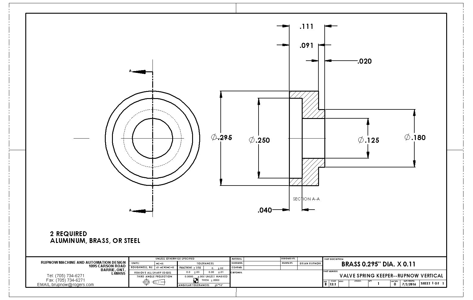
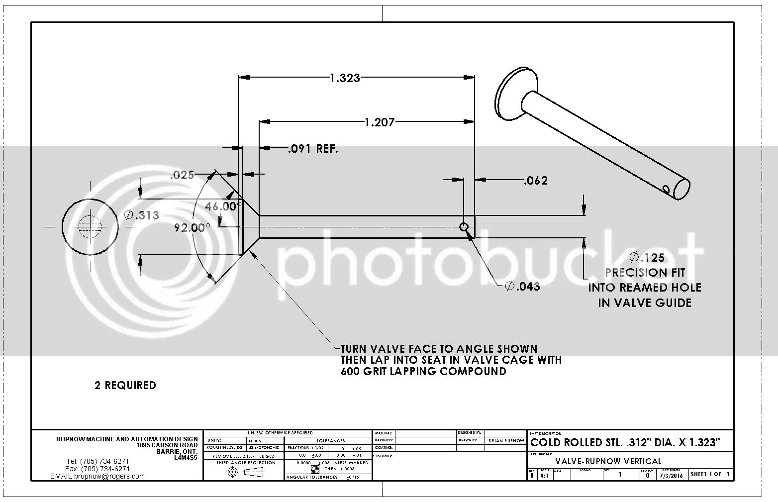
 http://i307.photobucket.com/albums/nn294/BrianRupnow/CONTINUATION%20OF%20MAIN%20ALBUM1/ALBUM%20THREE/VALVE%20CAGE-RUPNOW%20VERTICAL_zpsqsjzfvjk.jpg[/IMG][/URL]

Last edited:
Cogsy
Well-Known Member
As I said, I'm not sure how long it will take me, but I've made a start...


- Joined
- Jan 24, 2009
- Messages
- 554
- Reaction score
- 123
And they're off!!!! And, most likely, soon running!!!
Pete
Pete
Cogsy--That's wonderful--Hurrayyyyyy!!!---I lay in bed last night thinking about that cylinder head, and it's going to be a real toad-sucker!!! Before I thrust something on you guys that isn't do-able, I think I better build it myself to make sure it can be machined. Today will be cylinder head day, with "step by step' in process pictures.
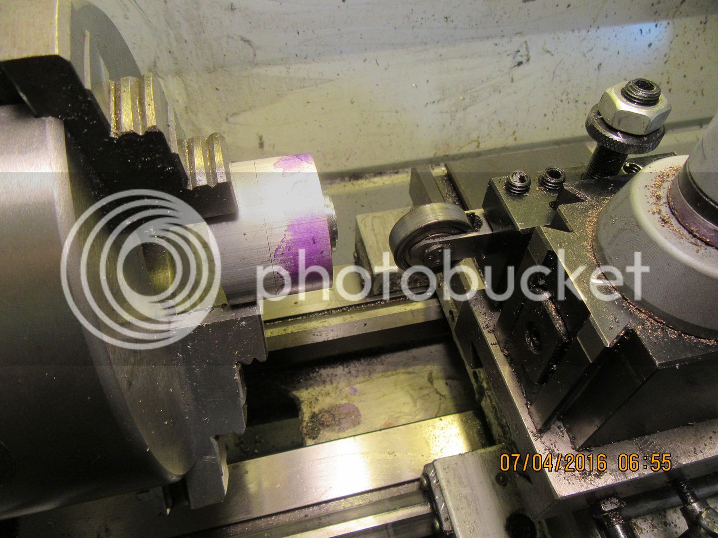
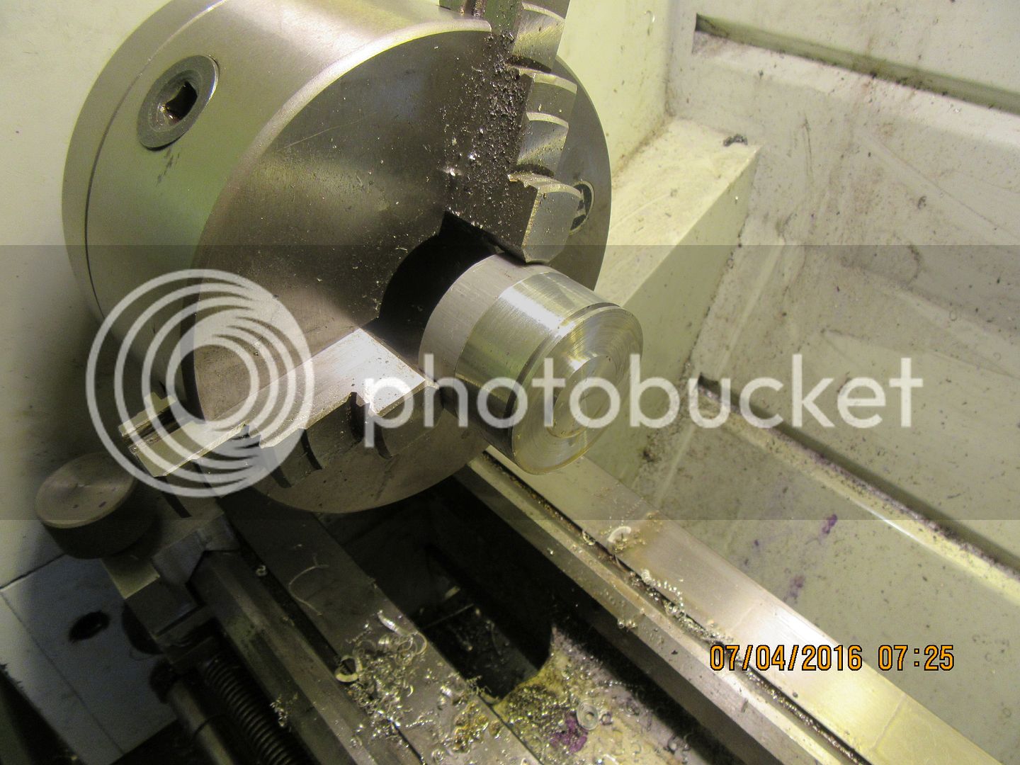
I rooted around in my bin until I found a chunk of 2' aluminum that was "just long enough" and chucked it up in my 3 jaw. Then I faced it, turned the 1" projection on the nose of it, and cut the single groove specified on the drawing. there is about .003" tir on my lathe, so I turned a "skim" off the o.d. of the piece to get everything nice and round.


- Joined
- May 27, 2010
- Messages
- 2,999
- Reaction score
- 1,171
George--For me to buy all of the components from Roy Scholl or a similar supplier, ends up costing me about $100 for all of the components, batteries, switches, etcetera, when I go the magnet/hall effect sensor route. If I just buy points and condenser and a switch, it costs me about $20.00. I have my "coil in a box" that readily transfers from one engine to another, and a small wet cell 12 volt garden tractor battery that does the same. It's just a matter of economics.---Brian
Hi Brian.
Plan to follow suit for all future engines. Ian Ridder use modify gas lighter with some minor modifications. Mini limit switch serves as contact point. Might try out Ridder's design too. Gas lighter cost peanuts.I am following you engine post. Engine looks simple. Will stop building complicated and unforgiving engines but they sharpen my skills.
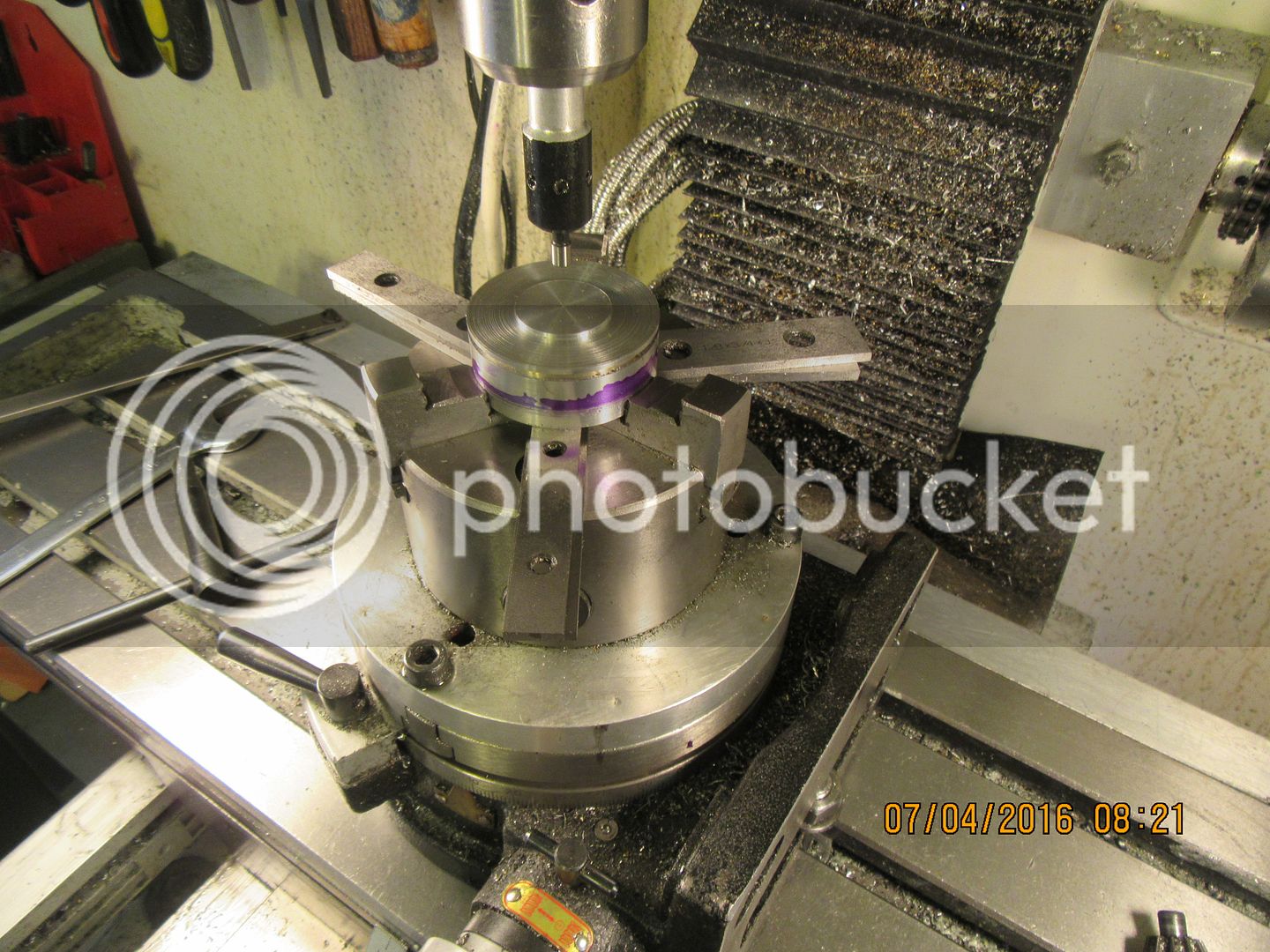
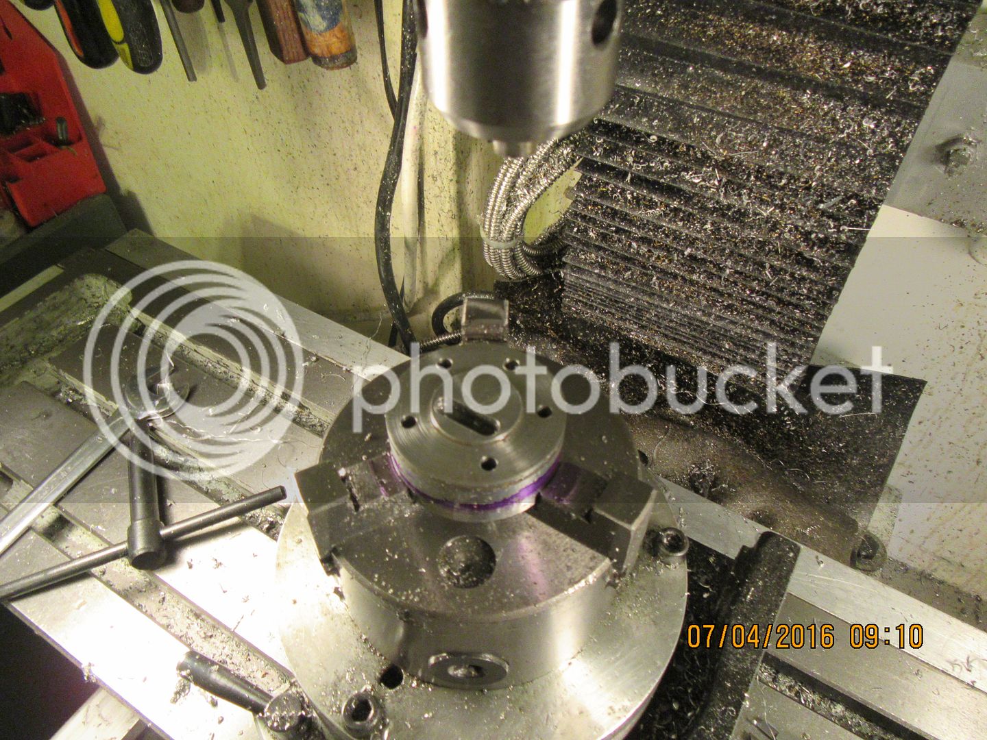
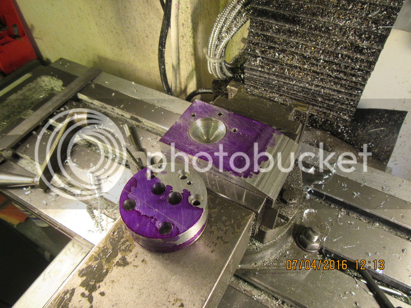
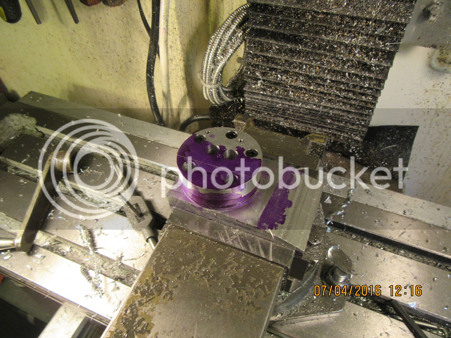
Okay--this is the end of "conventional' machining on the cylinder head. First step was to set it up in the rotary table chuck and center it under the quill. The "parallels" are simply spacers so that when I drill thru I don't hit the hardened chuck jaws with my drill. First order of operation was to put in the slot that the nose of the sparkplug extends into. After having done that, now the cylinder head has taken on "rotational characteristics' which simply means that any bolt holes put in after that have to be a certain distance in X and Y coordinates from the slot. Since there will be no way to see the slot once the cylinder head is flipped over for more operations, I won't be able to see the slot, so I put the thru holes in now while I'm in the same set-up. I will use the holes to align things when I flip the cylinder head over. I will also put the counter-bores in when it is flipped.


Hi gus--Glad to see you tuned in. I went in to tear down that last set-up, and fortunately I took a look at the drawing first and realized that I had to put in the bores and counterbores for the valve cages while still in that same set-up. Lucky I looked at the drawing!!!
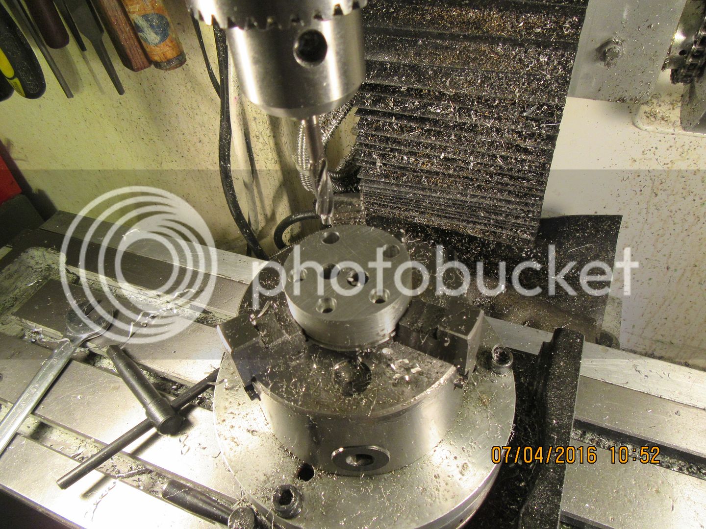
Here I have flipped the cylinder head over in the chuck on the rotary table, centered it under the quill, put a .170 dia. drill in the spindle chuck, offset the table 0.760" in the Y axis, then rotated the rotary table until the .0.170 drill will pass freely thru the existing hole. Now I have things located. Then I put a counterbore in the quill chuck and counterbore three of the holes to a depth of 0.164". The two remaining holes, which will end up in the slanted surface of the cyl. head get counterbored 0.476" deep. I have to drill and tap the two #6-32 holes that hold the rocker arm bracket, then the next step is where things start to get hinky.

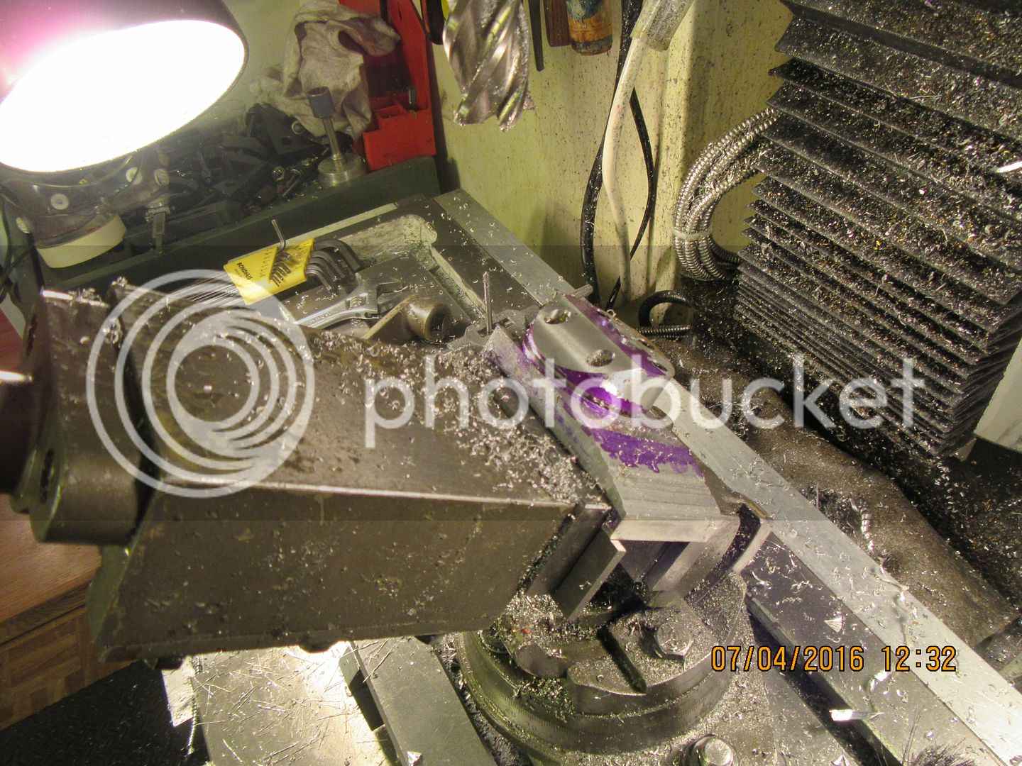
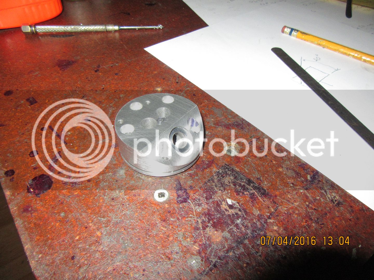
Okay--I promised you "Hinky"---we got "Hinky"!!! when I finished that very first step in the lathe, I had parted the cylinder head off from the parent stock to exact finished length. I dug around in my scrap bin until I found a short piece of 2" x 3/4" bar and mounted it in my vice. I drilled a shallow 1" clearance hole and drilled/tapped 3 holes that corresponded with the 3 head bolts which were not on the sloping surface. I bolted the head to the bar, and tilted my vice the required number of degrees to finish the sloping face and put in the sparkplug hole and counterbore. Don't worry if you don't have a tilting vice like mine---Just set it up at 90 degrees to what I did so you can tilt it up the required number of degrees in a fixed base vice. So--the head is finished. I'm sure it is the hardest part of this engine. If I can do it, so can you.
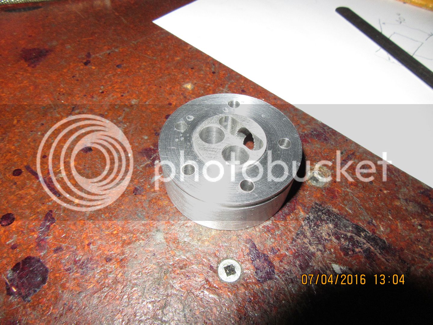


Last edited:
I ordered a set of Tecumseh points and condenser at Ideal Supply, and they will be in tomorrow. Also, looking at the solid model of this engine, I see a perfect set up for a small cooling fan driven by a friction wheel which is turned by the flywheel.
Cogsy
Well-Known Member
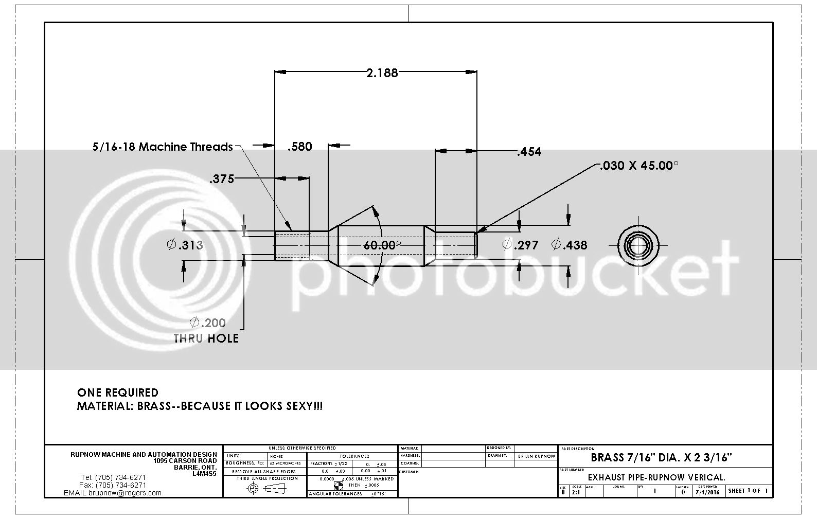
Hey Brian - on the exhaust plan sheet you spelled VER-I-COOL wrong  .
.
I looked at prices for the Tecumseh points/condenser on ebay and for an extra $5ish I can get a cheap Chinese CDI instead. Do you think it'll be reasonable for me to fit a hall sensor or will it be points only on this one?
I looked at prices for the Tecumseh points/condenser on ebay and for an extra $5ish I can get a cheap Chinese CDI instead. Do you think it'll be reasonable for me to fit a hall sensor or will it be points only on this one?
Cogsy--if you can make it work with a CDI, then by all means go for it. I'm picking my points up today to see what they look like.---Brian
Similar threads
- Replies
- 57
- Views
- 9K
- Replies
- 148
- Views
- 20K
- Replies
- 6
- Views
- 813


