Webster I.C. redesigned as hit and miss----

Home Model Engine Machinist Forum

Help Support Home Model Engine Machinist Forum:

This site may earn a commission from merchant affiliate links, including eBay, Amazon, and others.
My Bad, Brian, I meant contrate gears. They are essentially a spur gear except the teeth are around the outside face of the gear and not the rim. There are also a similar kind that is canted at 45*, think bevel gear only the teeth are not the full width of the face. I do so hope this is not too confusing and I do apologize for what I have caused already.

BC1
Jim
 
Bearcar--I did a web search and found out what they look like. It seems that a lot of radio controlled cars use a gear like that on the rear axle, driven by a pinion on the driveshaft.
 
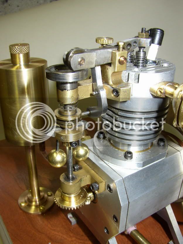
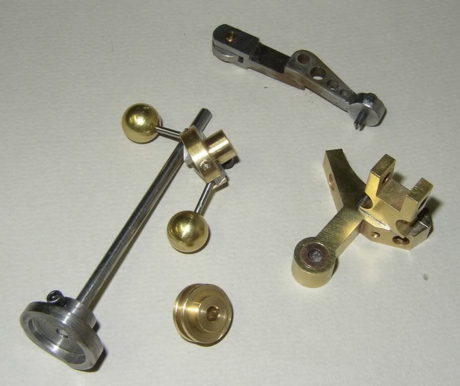
John----I know it sounds trite but---Size isn't everything---The valve spring on my webster engine which holds the exhaust valve closed is a very fine spring, only about 0.020" wire diameter. The attached images are of a "Silver Angel" i.c. engine with a 3/4" bore and stroke, similar in size to the Webster. It has large balls on it---probably 5/8" or larger. I know that with the governor I just built, it takes very little "spin" to make the balls fly out---but then again, the spring on the governor stempost is a very lightweight spring as well. This engine has a very unique vertical camshaft---and the cam is the round silver disc at the top of the vertical shaft. From remarks I have read by people who built this engine, the governor works very well, and since it is part of the "cam shaft", it would be rotating at 1/2 the speed of the crankshaft. One of the advantages that I see in driving the governor with a belt instead of a set of gears is that if the speed of the governors is to great or to little to be effective, it is a simple matter to change a pulley size. These neoprene o-rings will stretch to accomodate different pulley sizes, and have a relatively high coefficient of friction.
SILVERANGELFLYBALLGOVENOR-2.jpg

SILVERANGELFLYBALLGOVENOR.jpg
 
As I said Brian, only a suggestion.

But as you commented on the stretch of the o-ring, surely that points to too large a force being required.

If the 3/4" bore of that silver angel is in a normal relationship to the outer diameter of the cylinder, then I suspect that those balls be less than 1/2", maybe towards 3/8", but never having seen the plans, I can only surmise. Also there is a major difference between having a direct drive from the camshaft, or even crank, rather than the flexidrive you envisiage.

But I am not here to argue the point, I was just trying to maybe help a little.

Bogs
 
John---Your comments are always welcome. I don't take them as arguements. The o-ring elasticity is something I know about from stretching them over pulleys on various small engines. I haven't seen this stretch occur on any of the various gizmos that I have them on while operating, but I imagine that they do.---Its not really a visible thing. This entire attempt is going to fall into the category of "Try it and see what happens" engineering. Its entertaining, and as long as I'm not working with a pressure cooker boiler and don't get conked in the head with a runaway flyball, it should be fun. I know my Webster engine runs well. I know that this type of centrifugal governor works well from my first governor build a couple of years ago. Now its just a marriage of two seperate technologies that I know work to produce a third. One blessing----It doesn't cost much in terms of money, and if it doesn't work I may have a bit of egg on my face, but at least I won't have to deal with an angry customer.
 
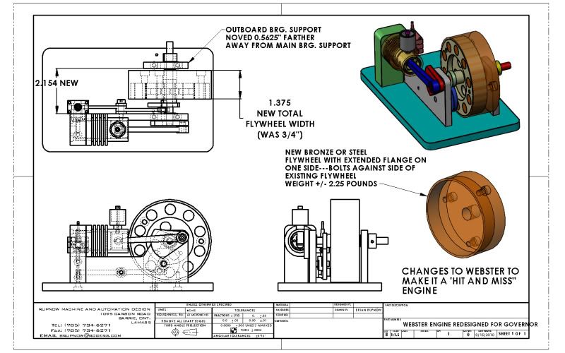
It begins---The first thing I have to do is change the flywheel weight on my Webster engine to be MUCH heavier. This is so that when the engine "misses" it will continue to rotate instead of quickly stopping as it currently does with its aluminum flywheel. I don't want to change the basic character of my engine. This is almost the ONLY change to the engine itself. I don't want to mess with the integrity of my current flywheel, because it has the one timing gear mounted in the side of the hub, and is pinned to the crankshaft with a pair of 3/32" diameter dowel pins. By doing things this way, I only have to move the outboard bearing support over a bit to make room for the new flywheel addition (This requires two new holes to be drilled in the baseplate.) The current flywheel is 3.75" diameter and the height of the crankshaft centerline is 2" above the baseplate. This will allow the outer diameter of the new flywheel "addition" to be 3 7/8" which will give me a rim 1/16" thick all around the original flywheel and still clear the base by 1/16". I will drill and tap the side of the old flywheel 1/4"-20 in 3 locations, and drill c'bored matching holes in the face of the new addition to bolt it to the existing flywheel. I REALLY would like to make this new flywheel addition from brass and polish it, but I'm afraid a peice of brass that big will cost a fortune. Steel would work as well, but it would be a pig to machine a c'bore that big in the side of it.--Of course it would be much, much cheaper, and I could paint it----
WEBSTERENGINEREDESIGNEDFORGOVERNOR.jpg


View attachment WEBSTER ENGINE REDESIGNED FOR GOVERNOR.PDF
 
Another alternative to adding a heavy rim
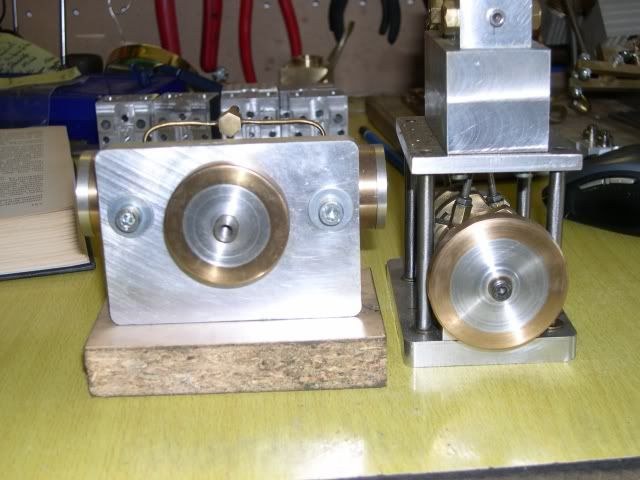
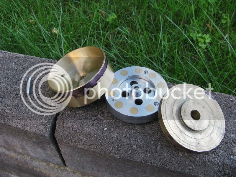
Flywheel_rims.jpg


The rim is made from a piece of bronze bearing material. It´s available in a lot of sizes, and is not very expensive in the amounts I´ve needed. It´s like a thick walled tubing.
In the above pic, the central part of the flywheel is ali, the rim is pressed on to the other, and Loctited (w. 270) to the other. You could also screw it through the rim.
I´ve done other flywheels the same way, exactly because it´s so cheap and easy. And I like the looks...
 
Hey Brian,
If what you plan to build is like the picture in your earlier post it looks to me like you plan to have the link from the governor modulate the exhaust valve. Most hit'n miss engines I've studied or built have an escapement that somehow catches the exhaust valve and holds it fully open until such time as the engine needs to fire again. I looked carefully at the picture of the little angle and notice it works exactly the way I discribed. On the little angle a finger slips under the lifter to hold it up. When the gov slows down it rotates the finger out of the way, allowing the valve to seat. I'll bet it works well. I think modulating the valve will not get you the results you desire.
 
jpeter---take a closer look at the picture---when the balls fly out and lift the lever at the yoke, the other end of the lever will tip down, moving a link which pushes down one end of a rocker mounted on the baseplate. The rocker pivots, and the other end lifts up and holds the exhaust valve off the seat.
 
So---We're at the point of no return. I went uptown to one of my steel suppliers this morning and spent half the Rupnow fortune (actually $70) on a big old chunk of brass, 4" diameter x 2" thick. This will become the new heavier flywheel addition for the hit and miss Webster.
BRASSFORLARGERFLYWHEEL002.jpg
 
Wow - A pound and a half ought to keep the webster spinning a while - assuming my arithmetic is right. Brass sure is getting dear. :-(
 
Look at post #25---As the drawing says, once this thing gets whittled to final size, we are looking at around 2 1/4 pounds.
 
Brian Rupnow said:
Look at post #25---As the drawing says, once this thing gets whittled to final size, we are looking at around 2 1/4 pounds.

With the price of brass, I'd figure out a way to whittle away the extra ~5 pounds in as big a single chunk as possible.

Chuck
 
Chuck---Right you are on that score. I have just faced one side, now I will mark out the chunk I need and try to bandsaw the rest away.
 
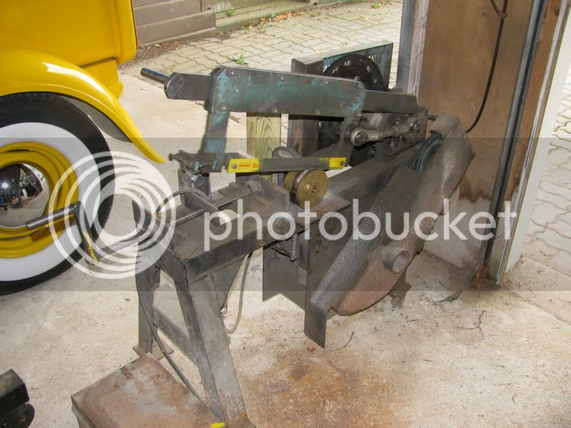
The bandsaw kept trying to rip the chunk of brass out of my hands, so I walked it out to the big old power hacksaw that I built about 40 years ago. Its sitting out there in the garage now chewing away---Makes a Hell of a racket, but the wifes at work so thats okay.
sawingoneoff002.jpg
 
I redid the math and get just over 3.5 kg using 8.5 g/cc. Looks like I failed to convert the length of the piece to cm when I did it the first time. Nice chunk of metal in any case. Hopefully several flywheels worth.
 
Brian Rupnow said:
The bandsaw kept trying to rip the chunk of brass out of my hands, so I walked it out to the big old power hacksaw that I built about 40 years ago. Its sitting out there in the garage now chewing away---Makes a Hell of a racket, but the wifes at work so thats okay.
sawingoneoff002.jpg

Brian,

You are such a tease.

Showing us just one corner of your street rod.

How about letting us see more of it.

SAM
 
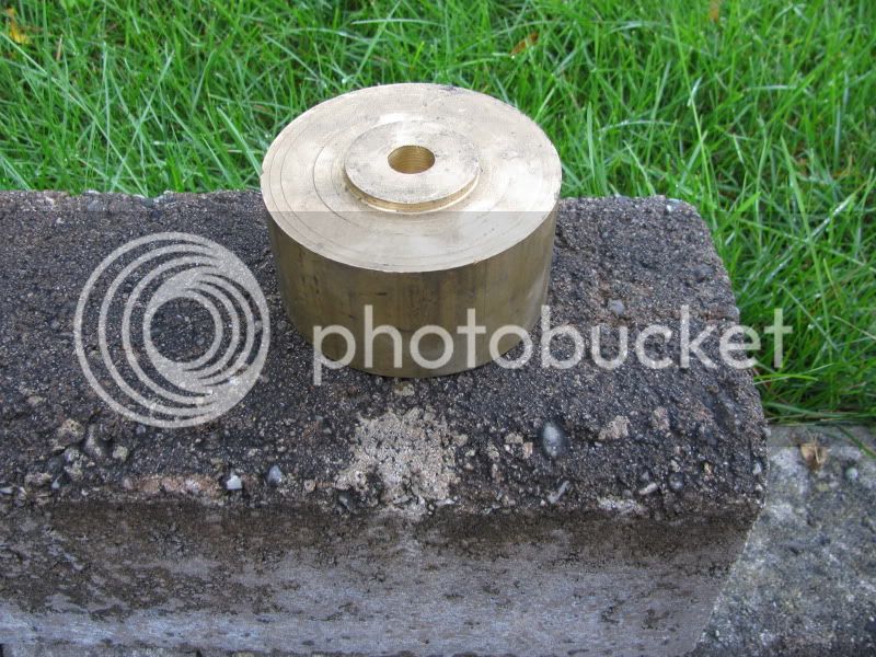
Well, that went very fine!!! I even have a peice about 7/16" thick left over. The new brass flywheel fits snugly over the existing flywheel and makes an incredible weight difference. Tomorrow I will polish the brass to a mirror finish and put the Webster back together and see what difference it makes to its "coasting" ability.
newbrassflywheel002.jpg
 
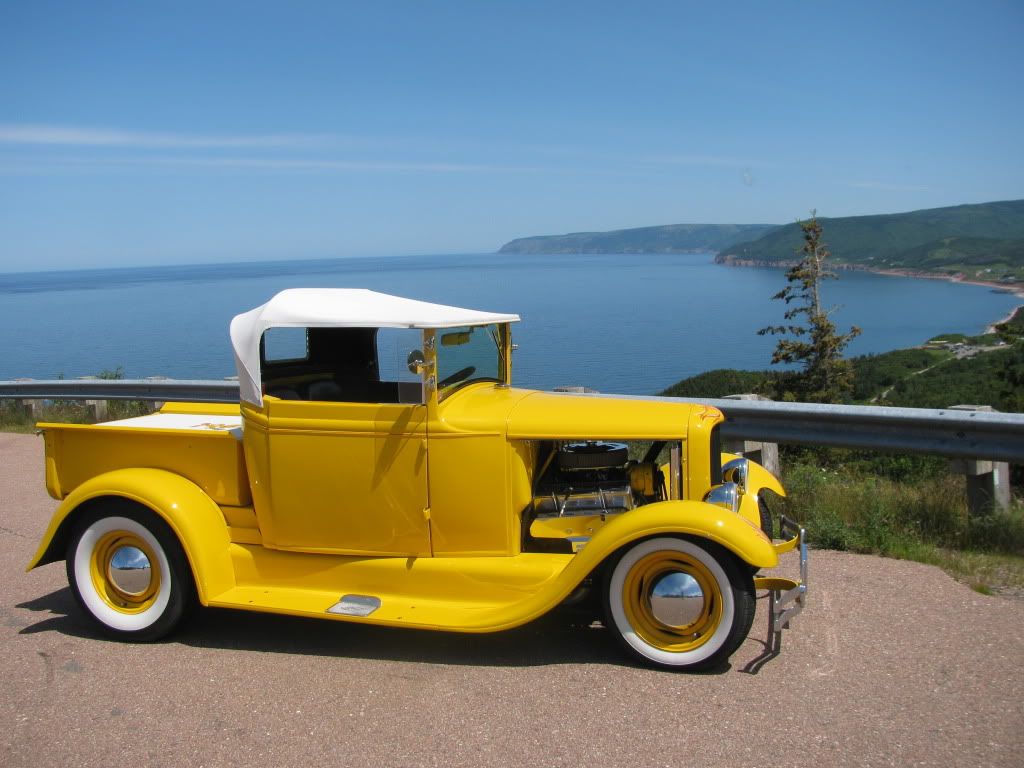
Here ya go Sam---This was taken last year on the "Great Canadian Hotrod Tour"--Somewhere down on the east coast of Canada---Cape Breton I think.
2009-NATIONALS086.jpg
 

Latest posts

Back
Top