Webster I.C. redesigned as hit and miss----

Home Model Engine Machinist Forum

Help Support Home Model Engine Machinist Forum:

This site may earn a commission from merchant affiliate links, including eBay, Amazon, and others.

Brian Rupnow

Design Engineer
Project of the Month Winner
Joined
May 23, 2008
Messages
14,975
Reaction score
8,266
Location
Barrie, Ontario, Canada
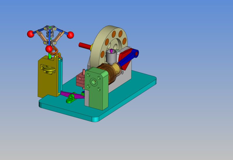
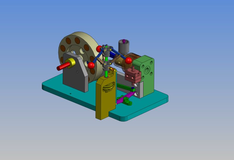
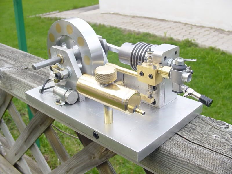
Last year, I built a Webster I.C. engine from plans that I downloaded off the internet. http://www.homemodelenginemachinist.com/index.php?topic=8388.0 They are a great set of plans, and I am most impressed with the engine. I haven't machined much lately. Its summertime, and the hotrod cruise/show season is in full swing, and my (other) hobby, a 1931 model A roadster pickup has been filling my spare time. BUT----I 'bin thinkin'------
I think hit and miss engines are kinda neat. I built the Chuck Fellows hit and miss steam engine, and it performed well. Once I have built an engine, worked out the "bugs", and have it running well, its just not that interesting anymore. (after you've showed your wife, your kids, your grandkids, and any unsuspecting friends or neighbours that drop by---)
I've been looking at the Webster, and thinking---The thing that makes a hit and miss engine hit and miss is a function of some type of centifugal governor energizing a mechanism to hold the exhaust valve of its seat at high RPMs untill the engine slows down, then the exhaust valve is allowed to seat once more and the engine fires again untill the RPMs pick back up again.
Now if I was to move the gas tank, and run a jackshaft in a set of pillow blocks in the spot where the gas tank now occupies, and drive it with a chain drive, and the jackshaft had a set of bob-weights on it and a lever---and the exhaust valve lifter is right there close at hand---Hmmmmm----Food for thought----
gastankinstalled004.jpg
 
Ehe, this has all the trappings for using another "BRIANS FLYBALL GOVERNOR", only slightly modded... woohoo1
Go for it, it would be a nice mod indeed. A chain drive might be just the ticket, it wouldn´t introduce any huge power losses. Or maybe a belt from the flywheel, to a small driven wheel, just to get the balls moving really fast.
Another one here who likes hit´n miss engines.
 
Brian,

Sounds like an interesting project!

Chuck
 
Thanks Chuck---I was hoping you would chime in here. I did a little research this morning---I fired up the Webster, and as it set there running on the bench, I snuck my long handled screwdriver in and held the exhaust valve off the seat---and the engine quit just like I expected it to. (I knew it would, but I still had to do that---I wear a belt and suspenders.) Now I just have to chew on methodology for a while before I begin to actually design changes.----Brian
 
I like hit-n-miss engines too. I'm looking forward to it.
I remember the Webster you did and the fun you had with the fuel tank.
 
I'm new here so my comment might not mean much. But anyway; that engine looks a lot like a Duclos designed hit'n miss called Maverick but with timing gears. He had an interesting approach to the governor. Its hard to discribe but photos are available on the web. Check it out.
 
Dang, this could get interesting.--the entire concept would be to make all the peices for making it a "Hit and miss" simple bolt on peices. That way it wouldn't ruin the engines original ability to run as a non hit and miss engine if I wanted to change it back. I haven't shown it, but I would put a pulley on the crankshaft of the Webster engine and drive the governor puley with an o-ring drive belt which is twisted though 90 degrees the same as on my twin horizontal steam engine. You will also note that this time I would build the governor as a 3 ball unit.
WEBSTERWITHGOVERNOR-1.jpg

WEBSTERWITHGOVERNOR-2.jpg
 
Nah, it isn't going to work, and here's why. My Webster has an aluminum flywheel. I drilled it and inserted a number of brass plugs to make it heavier, and it performs quite well to run the Webster in its current form. However, its simply not heavy enough to keep everything rotating if it "misses". It only has to "miss" once, and it very quickly comes to a stop. Not enough rotating mass to make things work as a "Hit and Miss" engine. I could move the outboard bearing support over and machine a wider, much heavier flywheel from steel, but that goes beyond what I want to do modification wise. I'd be further ahead to simply design and build a new hit and miss engine from scratch. I hunted around and found Philip Duclos' Maverick engine, and it does look pretty impressive. Does anybody have information on this engine? Are the plans available?---Brian
 
Brian.
Hey hey hey. That's some good ide. Why not put up the drawings of the governor on the download section and I(and surely others) will give it a try. Me have a steel/bronze flywheel and i think I have the mass that's needed.
I have had thougts on making a governor for my Webster, but this is some great plans.
Best regards
CS.
 
Hi Brian,
You may be right with the ali flywheel not having enough momentum. Many hit and miss engines have 2 rather heavy flywheels, just to get enough mass swinging, of course. Would there perhaps be room enough to make a brass/bronze rim around your present flywheel? Maybe milling some space for it from the baseplate? There would seem to be space enough between the bearing supports for a somewhat wider rim. Even a rather thin rim of bronze would work wonders, I think. Even better
would be a lead ring, of course. Gold would be ideal... stickpoke
 
Crankshafter Way back in the distant past, I did a thread on building a 2 ball governor. I can't remember now whether I actually posted a thread on the 3 ball governor or not. Only a couple of the parts changed. I am not going to turn my Webster into a hit and miss for reasons stated. I am however, building a 3 ball version of the governor right now, just to put in a boring afternoon. I will start a new thread for that.---Brian
 
Brian
I'm seeing forward to your 3-ball governor wrightup :bow:
CS.
 
Brian,

I've seen several different builds of the Maverick and although it's one of his simpler engines to build, I've never seen one that I thought ran very well. I would probably opt for his OddBall Six Cycle hit n miss engine.

[ame=http://www.youtube.com/watch?v=JZMpr2NFM5o&feature=related]http://www.youtube.com/watch?v=JZMpr2NFM5o&feature=related[/ame]

Of course, I also like his original hit n miss engine, the odds n ends hit n miss.

[ame=http://www.youtube.com/watch?v=-x1yxKnYLEA&feature=related]http://www.youtube.com/watch?v=-x1yxKnYLEA&feature=related[/ame]

Chuck

 
Hey, I built a Maverick and it runs great. I must admit I modified it to incorporate timing gears though; did away with the indexer.
A comment on the suggested governor design; seems most hit'n miss governors incorporate a catch to catch the exhaust valve and hold it fully open. In the plan shown it appears the gov only slightly holds open the exhaust valve, a much different approach than one would normally find. I question that design because the valve would never fully seat. The valve might overheat and be troublesome to adjust into the miss mode. Might be easy though to fashion an escapement to catch the rocker arm to hold the valve open.
 
I can't help myself----I'm going to do it!!! I checked today, and I can move the outboard bearing support over about half an inch. This will give me enough room to take a peice of 4" diameter brass or steel x 1 1/4" wide, hog out one side to 3.75 dia. x 0.75 counterbore, drill a 3/8" clearance hole on center, and slide it right over the existing flywheel and screw it to the face of the existing flywheel. This lets me keep the same crankshaft with no changes. That should give ample weight for the engine to keep rotating in a "open valve" state. I will have to machine a clearance pocket right below the flywheel to let me go from the existing 3 3/4" flywheel to the larger 4" diameter. I just finished building the 3 ball governor----I'm excited about this!!!
 
School me, my brothers---Do you think it falls into the world of possibility to drive a govenor on a hit and miss gasoline engine with an o-ring drive belt? It works very succesfully on my twin horizontal steam engine, but when it "fires" there is nowheres near the same blast of torque that you get from an I.C. engine. Now, methinks this could go two ways. First way, that sudden blast of torque when the engine fires is sure to make the drive pulley slip a little bit in the o-ring belt.--However, it will probably catch up fairly quickly, and speed the governor up enough to lift the exhaust valve and slow the engine down. Second way---those neoprene o-rings are very elastic. I'm not sure what the result of that will be, but I think it will be the same as the First case---the o-ring will stretch elastically during the power stroke, then quickly "unstretch" during the exhaust, intake, and compression cycle. The net result will be a bit of lag from when the engine "hits" untill it begins to "miss". I have spent some time today studying the "silver Angel" engine, which has a most unique vertical camshaft, driven off a horizontal crankshaft, thru a set of 90 degree bevel gears. The flyball governor is attached to the camshaft. This makes me think that "all things being equal" the flyball govenor should rotate at 1/2 the speed of the crankshaft, thus a 1:2 ratio on the pulleys. I know in my heart that I SHOULD be using a gear drive to turn the flyball governor on my engine, however the configuration of my Webster doesn't lend itself very well to doing that. It seems to me that in the dark recesses of my memory, I have seen "full scale" hit and miss engines on which the flyball governors were belt driven, but I could be making that up-----. I guess that if the belt broke, one could be faced with a "run away" engine. Thinking---thinking----
 
Brian,

In the near future, I will be building a large hit 'n miss engine, and on that it shows a belt drive to the governor.

I don't think it matters much whether it is gear or belt driven, but I would suspect that the size of balls would come into it. There is a fair amount of centrifugal force required to get even a small ball governor to spread it's wings.

Mine will be 2" bore, but the two balls on the governor are only 5/8" diameter. For my drive, I will be using a steel spring drive of about 1/8" diameter, but the 'toy' engine lads use smaller and more flexible ones for driving off their small engines. Maybe Cedge can point you in the right direction for those in the US.

I would consider making a much smaller governor, say with 3/16" balls. But that is just a suggestion.


John
 
Brian, this is a most interesting thread to follow along on. I was looking at the CAD drawings of your engine and it got me to wondering, what if you were to relocate the gov. closer to the crankshaft and use a set of convolute gears to drive the flyball spindle or perhaps even incorporate crankshaft as the spindle itself (of course the balls would then be rotating in a vertical plane). Either way the linkage would require modification in order to hold the valve arm. These are just some daydream ideas that ran through my mind, but I thought I would toss them out anyway. I'll be watching this unfold.

BC1
Jim
 
Back
Top