Webster I.C. redesigned as hit and miss----

Home Model Engine Machinist Forum

Help Support Home Model Engine Machinist Forum:

This site may earn a commission from merchant affiliate links, including eBay, Amazon, and others.
Today it was back to more machining and some trial assembly on the governor frame.---I'm getting there!!!
ASSEMBLYPICTURE001.jpg
 
Brian,

What a nice looking package you made with your governor assembly.

SAM
 
The bottom yoke on this flyball governor keeps evolving. Originally, I built it to move a pivot arm with a 3/16" brass pin in the slot. Then as I got a bit deeper into using it to work on my Webster engine, I decided it should have a pair of bearings in there instead to help take the load and run friction free. This afternoon I machined a peice of 1018 mild steel with a slot just large enough to accept 1/2" o.d. ball bearings, and press fitted the original lower yoke into it, along with some of my favourite 638 Loctite. Both peices were reamed to 3/16" diameter, then I inserted a shaft after applying the loctite to keep everything lined up true. I'll wait 24 hours for the Loctite to cure, then tap the shaft out and re-ream the assembly.
BOTTOMYOKEEVOLVING003.jpg
 
Brian, that picture of you & your mom is priceless. I bet the smile on her face is similar to the smile on your face when the new engine first pops over. I envy you being able to share life with your mom.
 
Sometimes I outsmart myself!!!---In that last picture I posted, the diameter on the extreme right of the lower yoke is supposed to be a seperate peice, with a set screw in it. I knew that!!! Anyways, I came down to me shop this morning and thought--"Hey---I could combine those two peices and make it all in one." It wasn't untill after I had machined it and posted it that I realized it can't be all one peice. Oh well, nothing damaged except my pride. I'll stick it back in the lathe tomorrow and machine the offending lump off.
3BALLGOVSETUPFORBALLBRGYOKE-3.jpg

3BALLGOVSETUPFORBALLBRGYOKE--BALLSIN.jpg
 
Very much enjoying this.
I've always liked governors and this thread is very educational for me.

Thanks for sharing Mom.
 
Zee---Thanks for looking and commenting--Putputman too. I have been thrashing away today at the fitment of all the parts, correcting the boo boo I made on the lower yoke, and making the lever with the ball bearings on it that rides in the yoke. Everything is going together very well, only a couple of levers left to make. No one in Barrie carries #5-40 set screws, so I have ordered a box of 100 that should be here in a couple of days. Meanwhile the assembly looks a bit like a porcupine with #5-40 socket head capscrews in all the holes that will eventually get the 1/8" long setscrews. My fingers are sticking to the keyboard ( residual Loctite) so I better go wash my hands before the keyboard and I become one.
SEMIASSEMBLED002.jpg

SEMIASSEMBLED004.jpg

SEMIASSEMBLED003.jpg
 
Brian, I have a question. Why do you have 3 set screws for the top yoke? Is it to keep the unit balanced or does it take that many to keep it stuck to the vertical shaft? Would only 1 allow the yoke to slip on the shaft?

Ron
 
Ron---I used 3 setscrews because there were 3 places available. Not much of a reason, but thats it. On the first governor I made, I had to do a lot of messing around with governor springs to get it to work right---and on it the yoke was soldered in place, which meant I had to completely disassemble the governor to change a spring. This time around, I thought I would make the top yoke removeable, which will make changing springs much easier. Probably one set screw would have worked just as well.
 
Congratulations to Brian's mom! Many happy returns and blessings.


Thanks for the answer Brian. We are all allowed a little artistic license. ;D ;D ;D

Ron
 
Brian,

Just found this and love the way that design has evolved. Can't wait to see it working! :bow:
 
Well guys---Its all assembled, and I must say, it seems to work fine. The mechanism works freely. I have installed it on a temporary base to show the "action" of how it works. In the first picture, the govenor is in a 'balls in" condition, which would indicate no engine speed, or a very low speed. the arrow drawn on the temporary base shows the "mousehole" which the exhaust valve lockout" hides in when the governor is in this condition. The face of the aluminum main frame with the 'mousehole" in it will set about 0.030" from the side of the rocker arm on the Webster engine.
finalassembly001.jpg
 
And here we have it in a "balls out" condition. Centrifugal force has caused the balls to fly out into this condition as the engine reaches a high enough RPM to overcome the governor spring. This consequently tilts the top lever, which through the chain of other levers causes the "exhaust valve lockout" to advance out of the front of the main frame and slide under the rocker arm on the Webster when it is in the "exhaust valve open" condition. This prevents the engine from firing, as it can no longer build up compression, because the valve is held open. As the engine begins to slow down (The large flywheel is keeping the engine turning over, even though it is not firing). The governor turns more slowly, and returns to a "balls in" condition as the govenor spring expands to its "normal" length. This retracts the "exhaust valve lockout" into the "mousehole" in the main base. Now that the rocker arm is no longer held open, the exhaust valve can close and the engine will fire again, picking the RPM up and repeating the cycle. I am really looking foreward t getting my #5-40 set screws so that I can do a test run of the governor, using my variable speed drill. I will post a video.
finalassembly002.jpg

 
Brian,
A lot of ingenuity there. I really like the concept and it will look neat out in the open when the engine is running. On a hit and miss engine the governor weights are spring loaded to return them to the closed position much like your governor has. There is also another spring on the locking arm that is adjustable to control the speed of the engine. You could put a small pin in your locking block and a block on the side of your governor frame with a spring spanning between the two. Attach the frame end of the spring to a screw through the block and you'll be able to adjust the speed of the engine while it's running. I'm attaching a picture of my Little Brother engine. You can see the lock arm with the knurled knob. Under this is a spring which the tension can be adjusted by turning the knurled knob.
George

LIL BROTHER5.jpg
 
George--I really appreciate you having a look at my project and offering some constructive advice. I'm not 100% sure that I understand what the second spring you refer to does. In my design, the governor spring and levers will also serve to retract the "exhaust valve lockout" device when the engine slows down. I see my single governor spring as having two functions. #1 it will determine at what speed the balls can go into a "balls out" configuration, and #2 it will retract the "exhaust valve lockout" pin when the engine slows down.
 
You're correct Brian except that the engine will only run at the speed governed by the operation of the governor. If you wanted to speed up the engine you would have to put more preload against the governor weights thus having to spin the governor faster to overcome the extra load. On a full sized governor such as on a traction engine some of the governors had what they called a sawyer's lever. This was a lever that was operated by a cord from the work platform. When the engine would bog down while cutting a log on a sawmill the cord could be pulled and this would overcome the action of the governor to give the engine more steam. This is the reverse of what I'm talking about but it illustrates that a steam engine running with a governor will only operate within the load characteristics of the governor. A hit and miss engine will do the same thing, run at whatever the preload (spring pressure) is against the centrifugal force of the flyweights. To increase the speed of the engine you have to put more spring load against the governor.
George
 
Thanks George---I kind of thought that was what you meant. One of the reasons that I went to ball bearings on the main fork/lever was that I was thinking ahead to a secondary spring somewhere in the system to either add its force to or subtract some force away from the governor spring, to fine tune the engine RPM. I thought that if I do that, it may transfer load back through the fork/lever and I didn't want friction to become a consideration with just dowel pins riding in the groove in the lower yoke. I haven't actually got that far in my design yet---I'm kind of taking a "wait and see if I need it" approach. One of the nifty thing about creating prototypes for myself----It doesn't have to be a completely finished deal right out of the box like work I do for customers. ;D ;D ;D
 
Ah, I understand that now George.

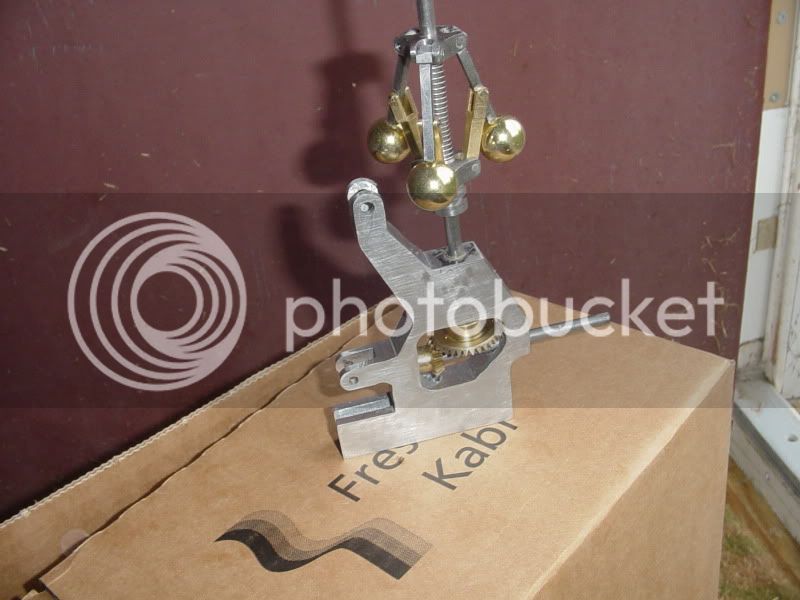
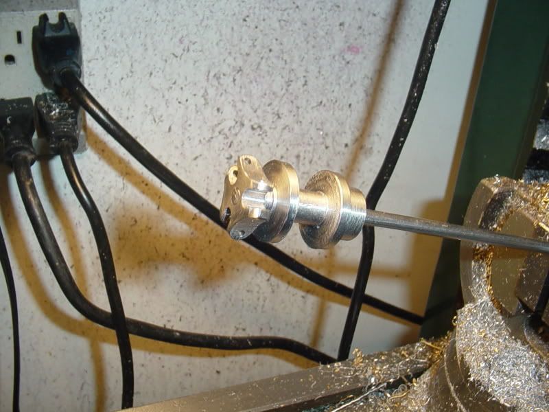
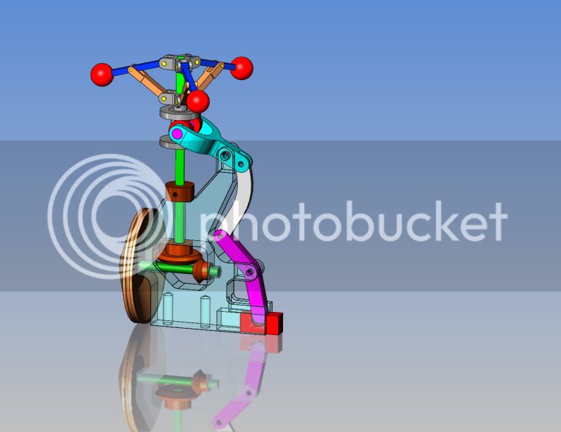
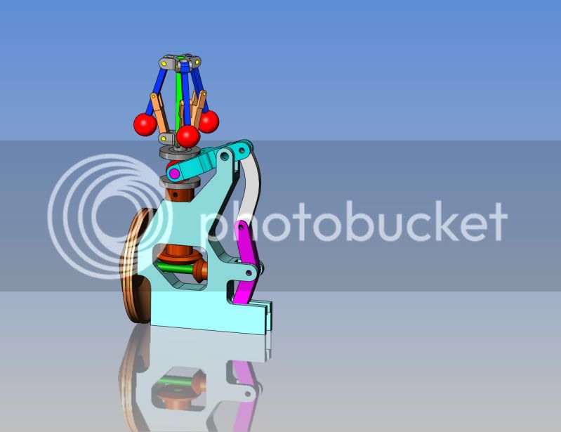
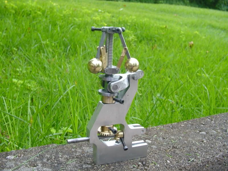
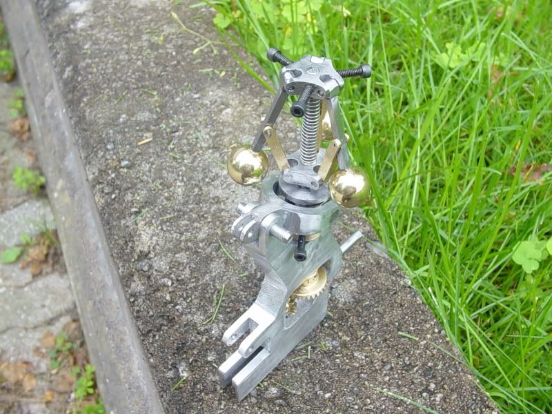
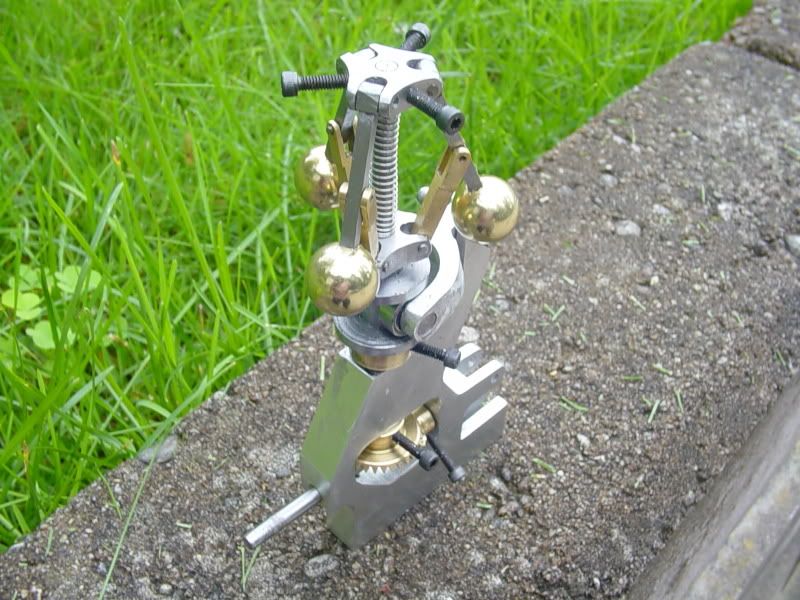
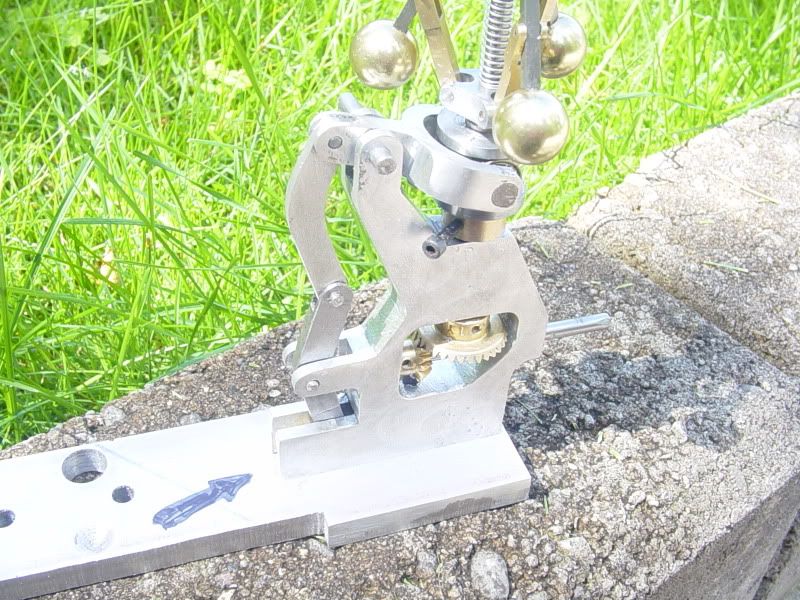
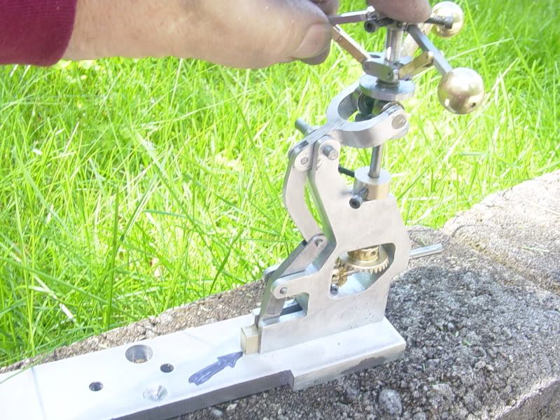
Looking excellent by the way Brian, It will be interesting to see your running experiments. How strong is that spring and will it be run 1:1 speed? Suppose you've already got a bit of reduction, apologies if I've missed it, what are the bevel gears 1:3 or something? The reason I ask is, the weight of those 3 balls and the spring +gearing, I think will cause quite a fair bit of drag and it might not 'miss' very much - i.e. it when it does miss, it will slow down quickly despite the heavier flywheel and hit again. I could be wrong but I guess there is going to be some tweaking of the spring pressure required, so George's idea of an adjustable tension could be a good one.


Latest posts

Back
Top