Vertical 4 cycle engine from recycled parts

Home Model Engine Machinist Forum

Help Support Home Model Engine Machinist Forum:

This site may earn a commission from merchant affiliate links, including eBay, Amazon, and others.
Today we have rocker arms and hardened rollers in the end that contact the end of the valve. I haven't made the correct pivot pins yet, but I can do that tomorrow. The rocker arms seem to fit okay-- I'll have a better idea about fitment when I make the pushrods.
LBA0aL.jpg
 
Today has been designated a "Lazy day". I'm waiting right now for some parts to come in from Roy Sholl to complete my electronic ignition. I haven't got the faintest idea of how I'm going to do this, but expect that I will attach the trigger magnet in either one of the flywheels or in one of the large camshaft gears. I have to get all the electronic components together and actually see them make a spark before this will become clear to me. I've decided that I will put one Viton o-ring on the piston, and checking the piston drawing shows me that I have room to do this. I have a suspicion that the flywheels are going to be a bit too light for an i.c. engine, but I have enough brass here to build the existing flywheels out thicker if I need to. I may cut my cams tomorrow. They have to be cut before they are hardened.
 
Today I set up my vertical mill, boring head, and rotary table with chuck, and made a practice cam from aluminum which had previously been lathe turned to the correct "blank diameter". This method of cutting a cam works very well, but since I only build 3 or 4 engines a year, I forget all the set up steps. I have written myself a sheet of instructions on how to do this, but every time I do it I have to read them instructions carefully and I usually make a "practice piece" to confirm that I understand them. This cam looks okay, so probably tomorrow I will cut the real cams from 01 steel.
hKQlyk.jpg
 
This morning I'm "puttering". I am about to machine a cam onto the hub of the large gear. I don't trust the thin flange on the hub to stay in place in the chuck while I'm machining the cam on the other end. I've had thin pieces like that pull out of the three jaw chuck while I'm machining them. So, if I left it bolted to the large gear, it won't pull out of the chuck.---But---There is no accurate way to hold a gear in a three jaw chuck. The answer is to machine a fixture which will hold the large gear securely, then clamp the fixture in the three jaw chuck while I machine the other end of the hub into a cam.
Kj12qs.jpg
 
The first cam has been cut on the 01 steel hub. These cams do have true radiused sides, but at this size they are hard to see unless you lay a straight edge on the side of the cam and check it against a light in the background. One down, one to go.
BVpmcS.jpg
 
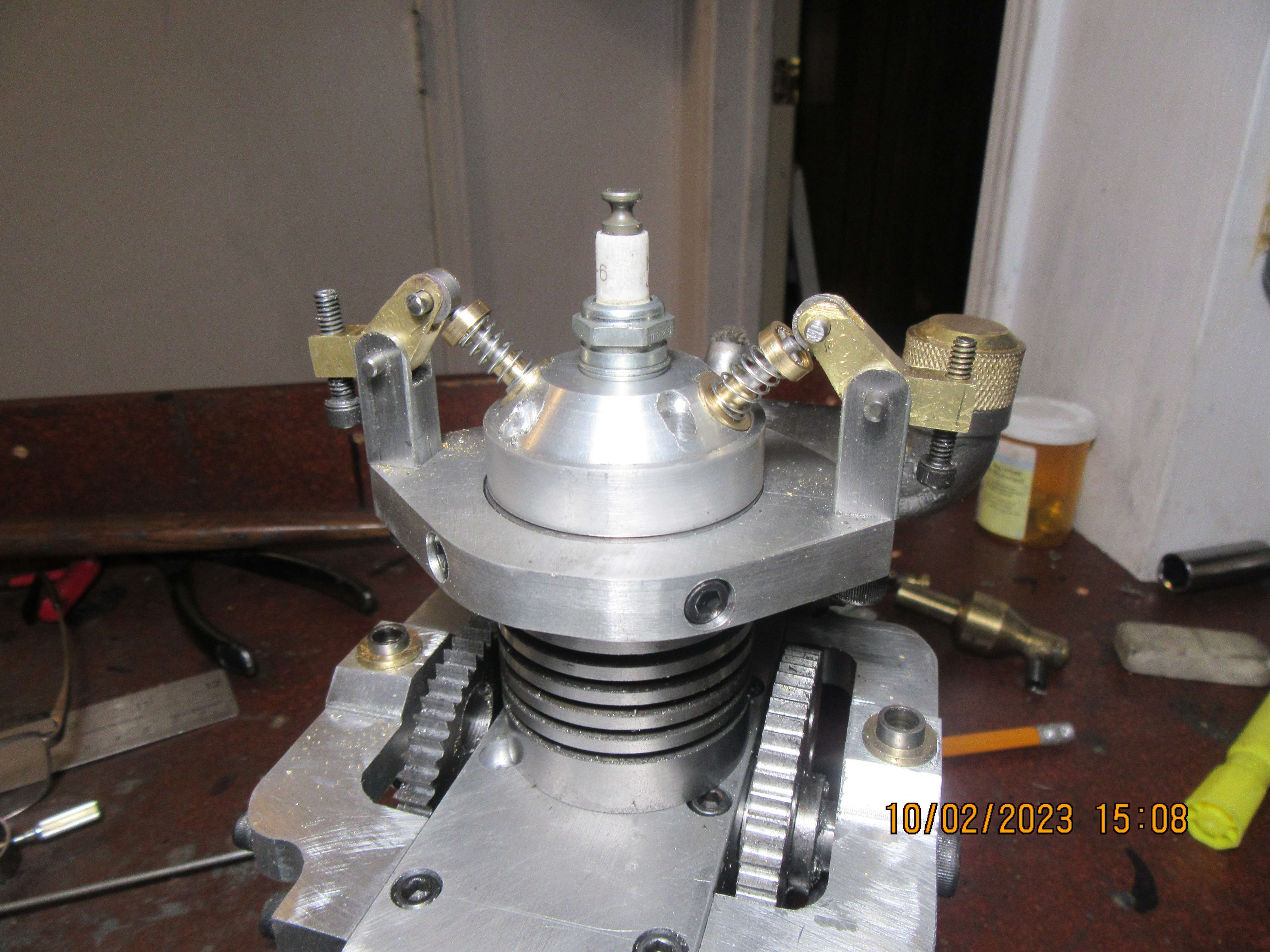
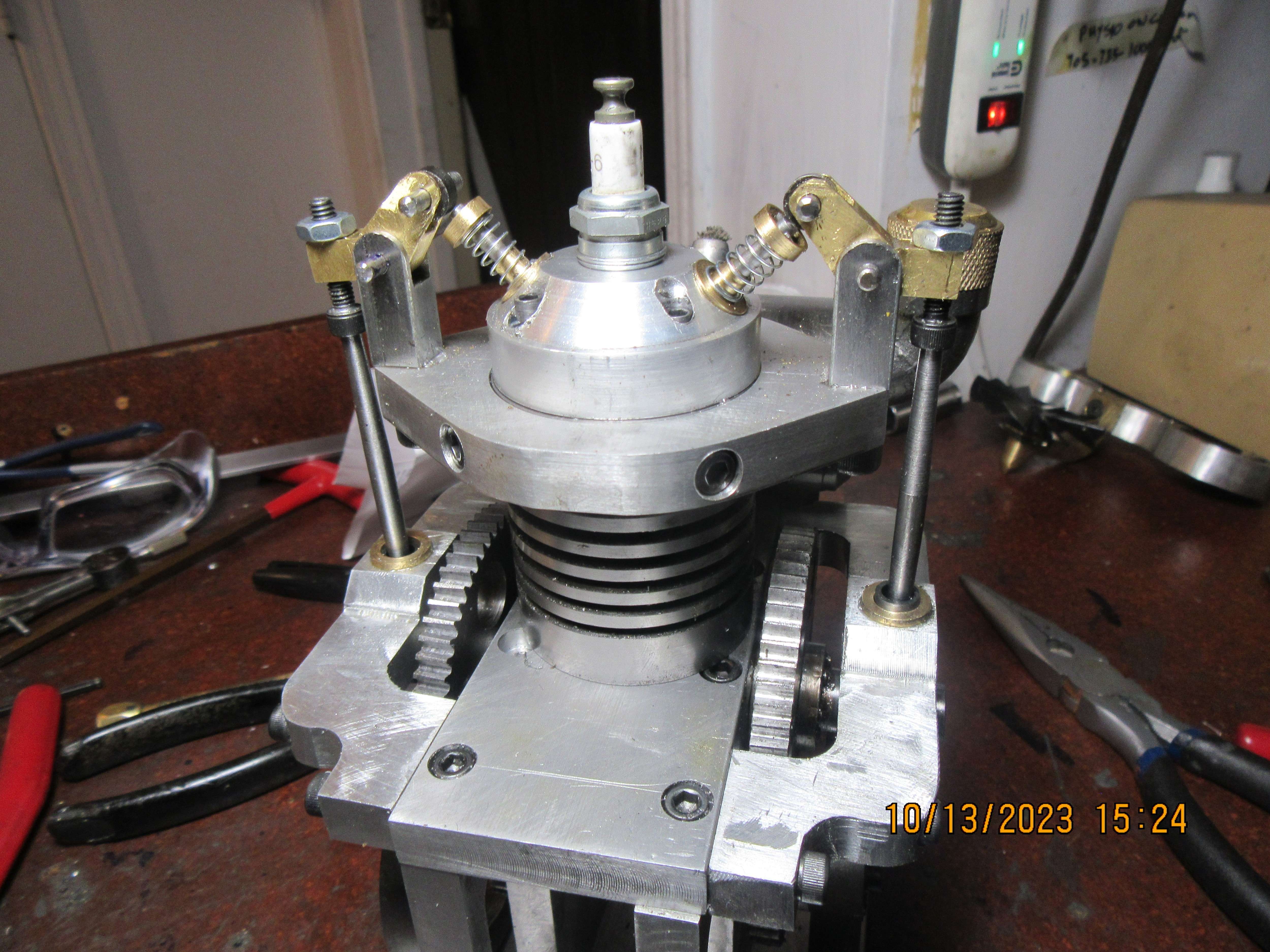
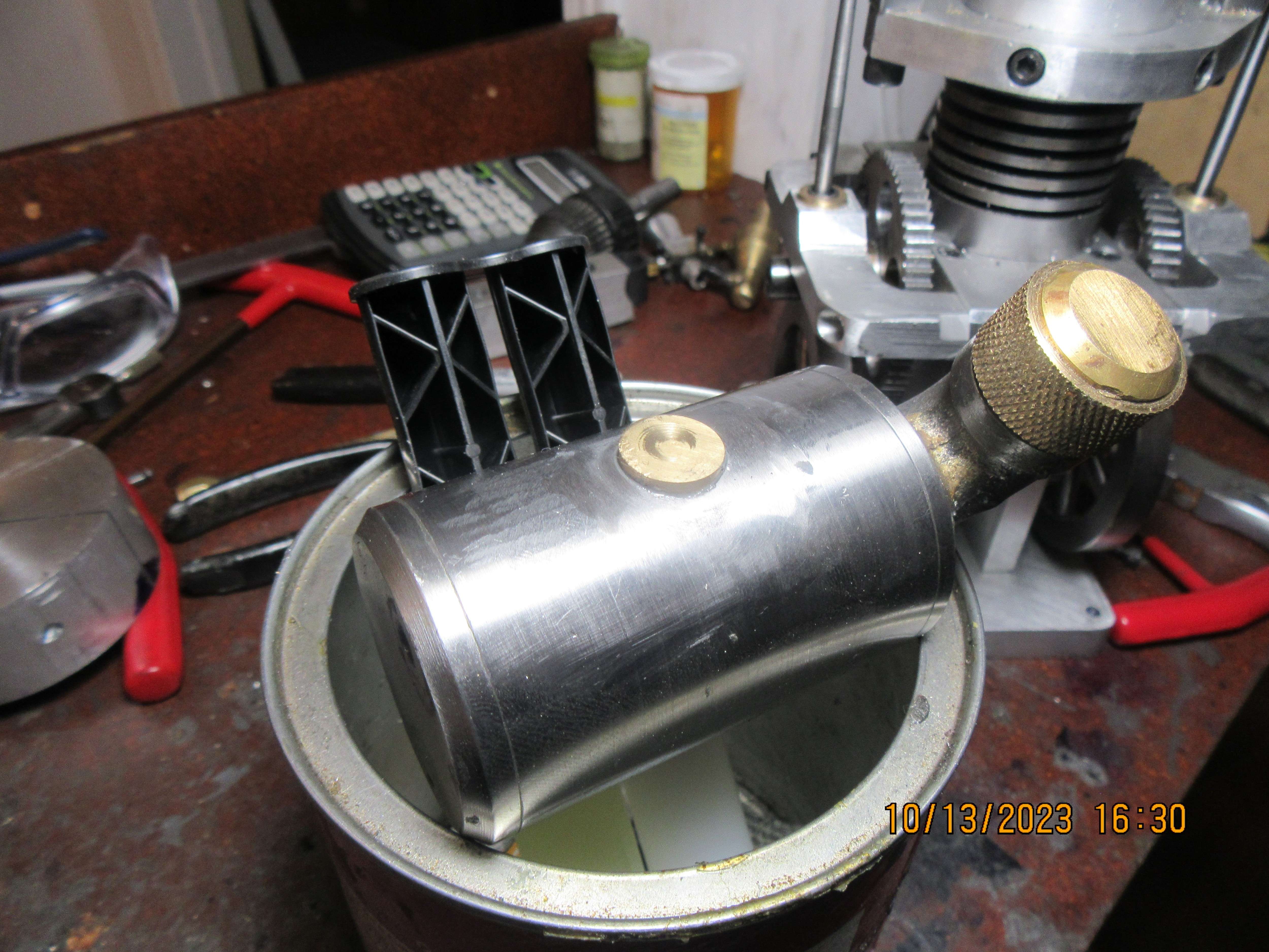
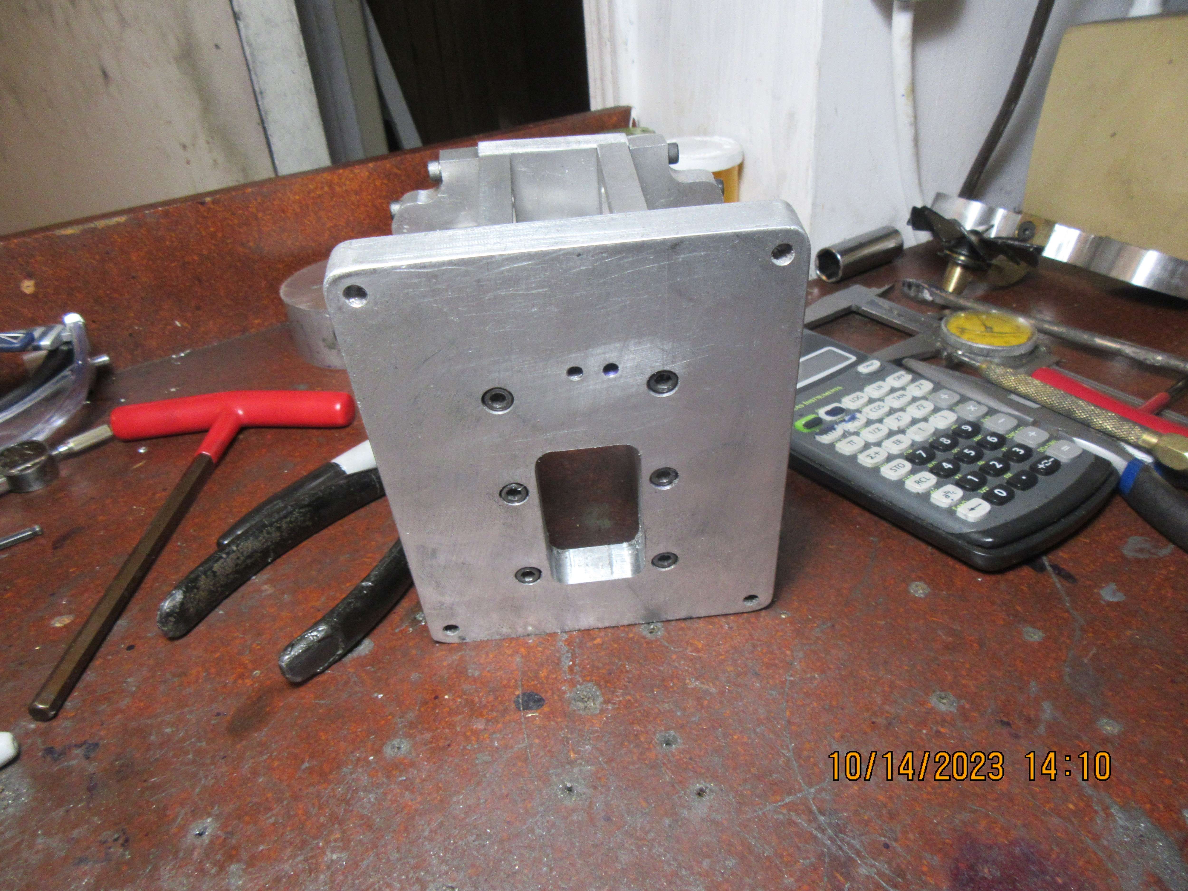
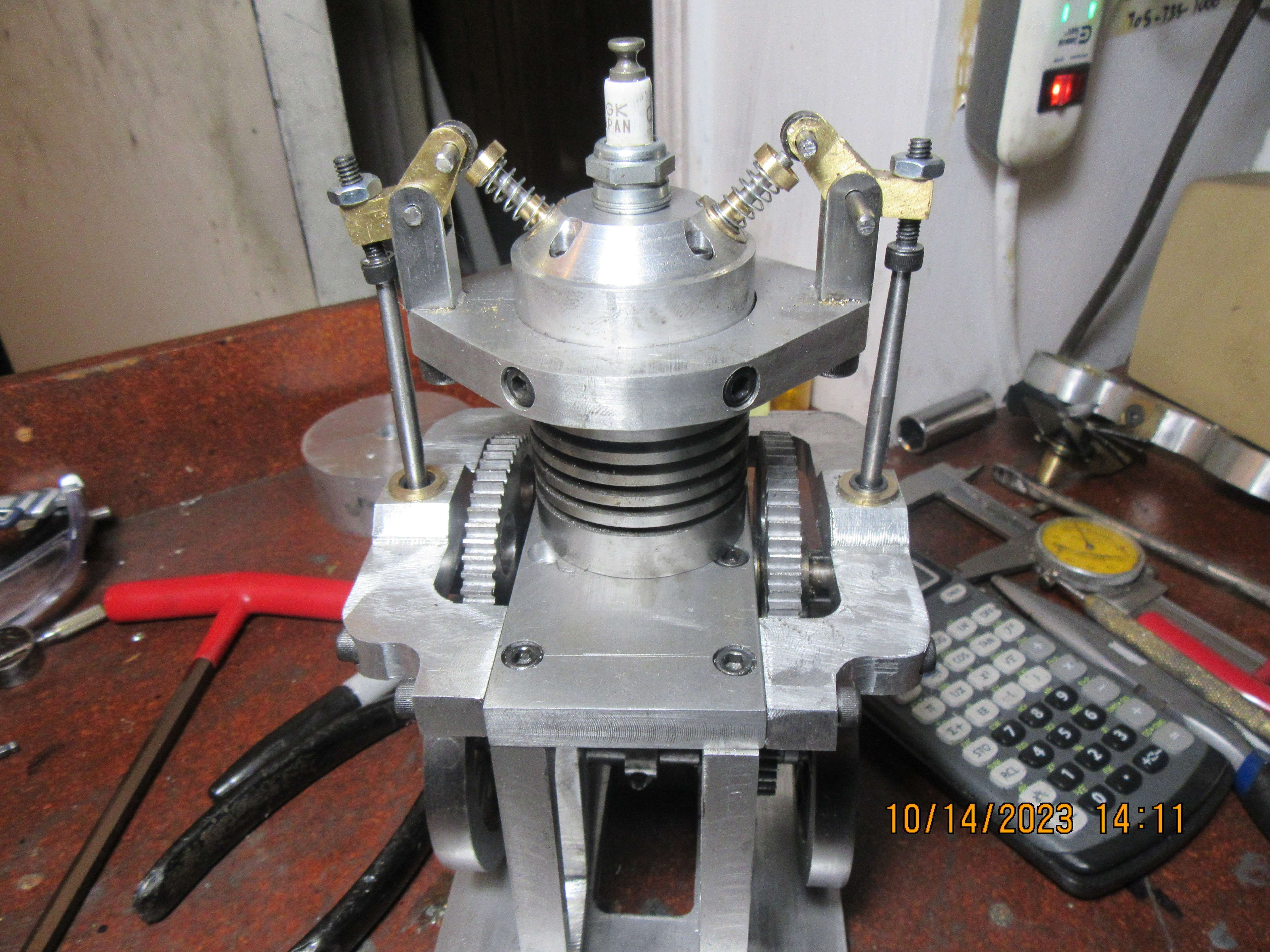
I've been feeling a bit off this past week, but today I hardened all of my 01 steel parts---the rollers on the end of the rocker arms, the tappets, and the cams. I didn't get much measurable distortion, as all the parts went back together okay. I'm still waiting for some electronic parts from Roy Sholl--He had shipped them out to me but something got screwed up at the border and they shipped them back to him. He has sent them out again and I expect them later this week or early next week. tomorrow I will make the pushrods and maybe groove the existing piston for one Viton O-ring.
 
Not a lot accomplished today, except for a fancy new pair of pushrods. As I expected, the valve springs I installed initially aren't strong enough. Those springs are intended to close the valve, rock the rocker arm, move the pushrod and hold the tappet in contact with the cam. I went down to Brafasco where I buy all of my springs, and got some bad news. They are no longer going to carry their selection of Ajax springs. There is another bolt source on the far end of town, and they also carry Ajax springs, so I have to call them and see if they are still going to carry them. I've been thinking about the electronic ignition from Roy Sholl, and it seems to me that I remember that the magnet has to fit into a non magnetic revolving part of the engine. If that is the case, I will have to remake one of my 60 tooth camshaft gears from bronze or brass, and glue the magnet into it.
enxKfL.jpg
 
One of the things I haven't talked about is the gas tank. It was originally an alcohol tank, and as so, it had a 'wick spout' in a location that doesn't work when it becomes a gas tank. I couldn't braze the hole shut, as the ends are epoxied into place, and heat to braze the wick hole shut would bugger up the epoxied joints. Today I milled away the wick spout and turned a piece of brass to fill the hole---held in place by J.B. weld.
GuckMf.jpg
 
You can get away with a steel gear, just use a longer magnet and let it stick out past the face about 1/8". I see the parts made it back to Canada so you should see them soon.
 
Today was the day to put a ring groove in my piston, to accept a 3/4" o.d. x 1/16" cross section Viton o-ring. The easiest thing for me to do was to mill a hole in the baseplate directly below the cylinder, then reach in with long Allen wrenches to undo the 4 bolts holding the cylinder in place, then the two bolts holding the rod cap on, and remove the piston and cylinder thru the top of the plate which the cylinder bolts to. The groove was machined into the piston, the ring was put into the groove, the piston and rod were then installed thru the bottom of the cylinder, and then everything was reassembled.
83e9ed.jpg

BbS0DX.jpg

KcEKFh.jpg
 
Today, I did a couple of things that really don't show. I cut a keyway into both ends of the crankshaft and into the hubs of both flywheels. The viton ring has been installed on the piston, and everything is very "stiff". To get around this initial "stiffness", everything is covered in oil, and I've made up an adapter for my mill to turn the crankshaft for half an hour to get rid of most of the stiffness.
 
Last edited:
I don't want to butt in here but there was a discussion either here or one of the other forums where it was stated that the width should be cross section + 20% and depth should be cross section x 95% and that is what I have been using with good success. A 1/16 O ring has a cross section of .070 so .070 x 1.20 = .084 wide and .070 x .95 = .066 deep. For reference 3/32 O ring has a cross section of .103.
 
Gordon--I'm sure that may work for you. I arrived at my figures by trial and error, and found that a typical 0.094" wide parting off tool works just fine with the dimensions I have given.---Brian
 
Today I drilled and tapped the cylinder head for the exhaust and intake tubes, made the exhaust and intake tubes, and assembled them with the carburetor I plan on using. My electronic ignition parts from Roy Sholl showed up in today's mail, and I was able to pick up the valve spring I had ordered from Brafasco. The spring is a little stronger than I had hoped it would be, but it only has to compress 0.100".
vwMBrE.jpg
 
Mechanically, the engine is just about finished. I think that the flywheels are going to be a bit too lightweight for an i.c. engine, but I'm not really sure. I guess that my best bet is to "try it and see". If the engine won't run, or won't run slowly enough to please me, I do have material on hand to make the existing flywheels thicker, and can gain about 1/8" on the outside diameter without hitting anything. I have my new electronic ignition parts from Roy Sholl, and tomorrow I will round up some batteries and see if I can figure out how to make a spark. I still have to add a fuel outlet to my gas tank (which was formerly an alcohol tank) and plumb it in to the carburetor. Also have to make a magnet mount which can be adjusted rotationally, independent of the large cam gears.
pFEjKG.jpg
 
Last edited:

Latest posts

Back
Top