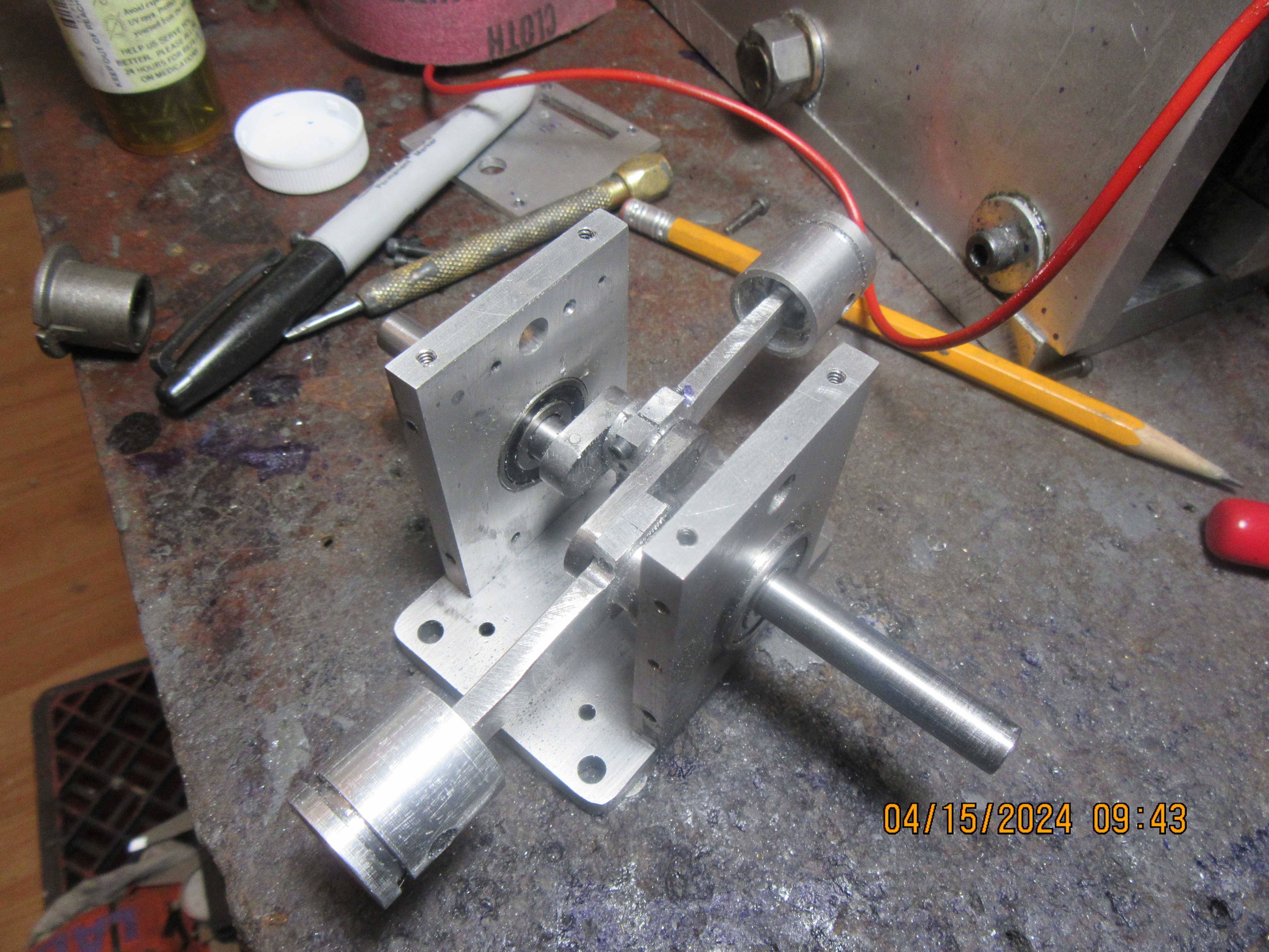
Looking good, Brian.
I will stick my neck out and suggest that to avoid marking up aluminum in a chuck, you cut a strip of soft drink can aluminum and wrap the piece in it before clamping.
The other point I'll make is that if I remember correctly, the original Upshur design leaked oil past the crankshaft. The solution was to use sealed ball bearings or put shaft seals in place.
Thats all I remember from others who built the engine (except the one guy who built it upside down whereupon it leaked very badly).