Tiny I.C. Engine

Home Model Engine Machinist Forum

Help Support Home Model Engine Machinist Forum:

This site may earn a commission from merchant affiliate links, including eBay, Amazon, and others.
Gail,
I wanted to let you know I got the package.
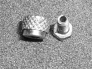
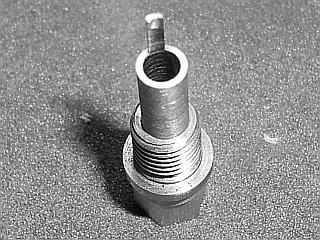
Thanks for the wire and the spark plug parts and the other stuff.
I got all my metal from Speedy metals and will start tomorrow afternoon.
I tell you with the price that Speedy metal sells there stock,I will buy from them from now on.
My wife had the mail in her car from yesterday and I just found the package.So quick shipping on that also.
Thanks for everything.
Tim
 
Gail;
I'll be watching for your test results re: higher performance engines and O-rings - I don't look forward to my first attempt at cast iron rings!

I've been slowly making small parts for an Upshur Twin (with BMW Motorcycle cosmetics), Ron Colonna's Offy and the Bentley BR2 - however I'm limited on the last two due to equipment (Taig lathe and X2 mill). Progress has been slow, I had a little go around with my heart and the emergency ward; plus moving into digs that are not machine shop friendly!

I'm living my dreams thru this website..... :big:

Keep up the great work - I'm silently watching and learning.
Garry
 
Well here's the latest update. I have the carb finished. I looked for some 1/16th ID tubing but couldn't find any so I went in a different direction. I made a hard line from brass. The carb end has a tapered cone fitting and the end that goes into the crankcase/fuel tank has a compression washer made from Teflon.
I finished one spark plug. I changed the size to 8-32 to make it a little more manageable. All that's left to do now is mount the Hall sensor, drill and tap for the timer arm and clean and polish the parts. I should be able to see if it will 'pop' within the next few days.
George

TINY CARB.jpg


TINY SPRK PLUG 2.jpg


TINY SPRK PLUG 3.jpg


TINY SPRK PLUG 1.jpg
 
Looks great, George.
I am shifting from looking mode to listening mode already.
Gail in NM
 
I'm with Gail, just waiting for that popping sound. Engine looks great.

I am also curious as how that spark plug will work set so far back from the cylinder. That will sure make it simpler in a lot of I.C. builds.

BTW, I have about 10 ft of the 1/16 I.D. tubing. If any of you Tiny I.C. builders need some, PM me with your mailing address and I'll send you a piece.
 
I just finished my "Tiny" this week, had it running and it runs good, but I still want to do some tweaking to it, but somehow I've managed to kill the hall effect sensor. I've got some on order, so until then all I can show you is some stills. Thanks Putputman for the plans, I hope my own changes are acceptable.
John

100_0454.jpg

100_0455.jpg

100_0457.jpg
 
John, that is just beautiful. All that brass really stands out. The base is very unique also.

On the middle photo, it looks like you might have a throttle control.

Looking forward to the video

 
Great job, John. Wouldn't mind getting a little more information on the carb (throttle control?).

Chuck
 
Thanks guys, Yes it is throttle control, thanks to a previous post by Kcmillin. I just followed what he did, basicly just lengthened the carb and added a barrel type valve. She idles down nicely, but between say 15% open and wide open there doesn't seem to be a very big difference. I'm not very inovative but I sure like to copy what I think is the best of everyone's build. I wish Gbrit would have started sooner, I love the way he beveled off the rear frame and made the timing adjustable.
 
John,
The engine looks great!
I like the way you slotted the head.Can't wait to hear it!
The base is fantastic with the bent piston.
Tim
 
I love your version of the Tiny!!!! I am particularily fond of the cylinder and head as I have been toying with the idea of an air-cooled version.
I was wondering if you made the cylinder out of aluminum with a cast iron sleeve or solid cast iron?
 
Thanks everyone, Greg by trade I was an electrician, so I don't have a good knowledge of materials and which is best for which application. I made the cylinder out of stainless steel, so I could get a high polish and not have to worry about it again, maybe not the best choice-I don't know --but it is what it is.
 
Well here's a video of the first running. It's not very long but I am still tinkering with adjustments. I don't know where to set the timing. I have had it all over the map. I started about 5* before TDC and it wouldn't keep running. I kept advancing it and found a spot at about 20* BTDC where it seemed to run best. The carb was built to the drawing specs and I can only get about 1/4 of a turn from not running to running too rich. The compression feels good but I think I might make a new piston to increase the compression ratio a small amount and see it that helps.
George
[ame]http://www.youtube.com/watch?v=9R-ZcnXvVpE[/ame]
 

Nice job George!
 
Congratulations on another runner, George. Thm: Thm:

I had to change my fuel mixer to get increased adjustment range. When I started I was at the "I think I moved it" stage for going from to rich to too lean. I opened up the longitudinal hole from 0.018 to 0.020 with a #76 drill bit and used a #10 Sharps sewing needle which measured 0.0195 for the needle. Measure the needle if you do this as I found some variation in diameter. This let the needle form a narrow passage to let the fuel flow through. I now have about 1-1/2 turns of operational range.

My timing is not adjustable on the fly, but did not seem to be very critical in between run adjustments. It is currently at about 10 degrees BTDC, but I can't tell the difference 5 to 10 degrees either way. I would like to make up an adjustable timing like you did sometime just to see what happens real time.

My compression is 5.6 to 1 currently.

Gail in NM
 
Congratulations George! :bow:

Its great to hear it running, and it sounds really nice.

It runs real good to, even with out a head gasket. stickpoke

You never cease to amaze me! Thm:

-MB
 
As always George that is a sweet little engine. My needle valve adjustment also seems to go from lean to rich in a quarter turn or less. I've been running my timing around TDC, will have to bumpit up a bit and see how she runs. After I get my new hall effect and change it out. Your's seems to rev a little faster than mine, any idea of the RPM ?
John
 
Great Job George! It runs as good as it Looks! I love the sound, in fact when I seen your first post of the muffler I secretly made one similar, to see what it was going to sound like.

My experience with the time is like everyone else, all over the place. I even had it running by timing it for ATDC up to about 15 degrees or so. I currently have it about 15 BTDC. The mount I have allows about 10 degrees of adjustment while the engine is running.


John, I have recorded RPM's from anywhere between 1200 and 7200 RPM. When I take the tach off the crankshaft it spins even faster, my estimate about 8000 RPM.

Kel
 
A couple of members wanted more information on my spark plug. Attached is the drawing of my current spark plug in PDF format. This is my working drawing and not polished. Ignore the 4 place decimal. Thats just how I do my working drawings and should not be taken as high precision being necessary.

The photos are of the parts as machined and forming the electrode. I did not take any photos of the machining operations. The only thing unusual is the milling away of the extra housing length to for the ground electrode. I gripped the body on the hex in the milling vice and then used a 4 flute 1/8 end mill to remove the extra material. I took 5 passes on each side starting at the top and removing about 0.035 material on each pass. Cut one side and then the other before down feeding the cutter 0.035 for the next pair of cuts.

The electrode was formed over a scrap of 1/16 sheet metal with the edge broken to give a slight radius. I bent the electrode over with a scrap block by hand and then tapped it down with a small 4 ounce hammer. I could not hold the sheet metal form in place well enough so it slid away some, but the electrode was squared up later after assembly and the final gap set then

The assembly operations will be in the next post (or two).

Gail in NM

Spark-001.jpg
Spark-002.jpg


Spark-003.jpg
Spark-004.jpg


Spark-005.jpg


View attachment SPARK.pdf
 
Assembly starts with soldering the 0-80 screw to the end of the electrode. I used some 0.015 electronics solder to form a ring. Solder ring slid on the electrode and the end of the electrode is dipped in flux. Screw slid on and the ring slid up to the screw. ZHeat gently with a small torch until the solder flows. Doesn't take long with parts this small.

Spark-0001.jpg
Spark-0002.jpg


After cleaning up the excess flux and any extra solder, the electrode is ground to final length. Insert the electrode in the insulator. Measure the length from the top of the screw to the insulator. The electrode wants to be about 0.015 longer than this. The photo shows before grinding with the wire protruding about 0.093. Remove the electrode from the insulator and grind off the end until the end will protrude about 0.015 inch. If you go too far then shorten the electrode big end a little bit.

Spark-0003.jpg
Spark-0004.jpg


Back
Top