tiny four cycle

Home Model Engine Machinist Forum

Help Support Home Model Engine Machinist Forum:

This site may earn a commission from merchant affiliate links, including eBay, Amazon, and others.
KK,
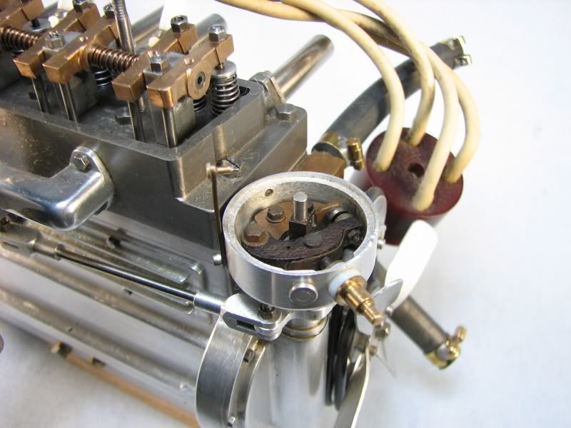
As far as I know, music wire and piano wire are the same animal. Used lots of the stuff in model airplane and heli building. Are you doing this like an old timer engine with the cam and points right behind the prop?
Tony
 
Yes everything comes out the same end.
You said the C word. :hDe:
I have never built a cam and hopefully everything goes well. :shrug:
I have the plans for a cam cat but I think this one will be too small for it, maybe just a file.
I am working on the keepers now and the rocker post/arms
I hope I dont bend the valves cutting the slot for the keepers.
Should I harden the valves the seats are aluminum.
-B-
 
KK,
I know, the C word scares me too (especially on the V8). My first cams were on the H/M in my avatar. One for the points one for the exhaust. Cut a disc the overall dia (with the rise)
Put in hole for shaft. Now blue it up and draw the low cam arc (opposite the high point) and the hih point arc. Connect with straight line to tangents. Mill down to almost the straight line both sides. I had a radius cutter close to the lower arc. Now you have a caveman cam. Put on mandrel and chuck her up. Set up parting tool at 90 and bring up to lower arc (what you say) Now you hand turn the chuck back and forth taking light cuts from tangent to tangent. Once round you can work the rest of the cam with a file and 220 paper like shoe buff style. Using the chuck as a vise. I know you have a more difficult cam to cut but I hope this helps a little
Tony
 
That helps, I need to get a roto table that would probably help. I could use cnc but I said I wouldnt use it on this build.
-B-
 
Krown Kustoms said:
Yes everything comes out the same end.
You said the C word. :hDe:
I have never built a cam and hopefully everything goes well. :shrug:
I have the plans for a cam cat but I think this one will be too small for it, maybe just a file.
I am working on the keepers now and the rocker post/arms
I hope I dont bend the valves cutting the slot for the keepers.
Should I harden the valves the seats are aluminum.
-B-
KK
if it where me I would not bother harden the valves. Bending the valves is not funny at all, if you look in the "Work in Progress-My Hoglet you will see a perfect valve, that was before I chuched it and made it "perfect" for a Sidevalver ;D
CS
 
I made a set of point for my 4 cylinder OHV engine. The movable arm is made from the insulator material from a switch panel. It has a small hardened roller that runs against the cam. The points are tungstens from a set of motorcycle point that are ground down to the required size. I don't think you can make them much smaller than these and have them work efficiently.
gbritnell

4cyldistributor.jpg
 
Those points look pretty good, I think mine will stay exposed.
I was going to use some .125 tungsten from my TIG. That stuff is pretty tough to cut, I have to use a diamond wheel to shape it for welding.
Thanks CC I will leave the valves how they are. I still have to take out .010 for the keepers.
-B-
 
zeeprogrammer said:
Spark plugs...aren't they like diamonds to a girlfriend/wife/partner?
I didn't think much about them until I saw people making them on this forum.
Guess that makes me a....

Girl? ???
 
Well I made the post for the rocker arms, well partially until I saw the screw was too short.
So another part to the scrap bin.
I may be able to salvage it if I can get the loc-tited screw out to replace with a longer one.
-B-

DSC02081.JPG


DSC02084.JPG


DSC02084.JPG


DSC02085.JPG


DSC02085.JPG
 
Well I was able to salvage it now off to the rocker arms, keepers and springs, after seeing CS's bent valve Im scared to cut the notch for the keepers.
-B-
 
Here's what I would do to cut the recess for the keepers. Take a piece of brass rod that's a little larger than your valve head and drill and ream it or if it's not a standard reamer size just progressively drill it up to size and finish with a new drill bit. Now cut it off just long enough to slide the valve in with enough of the stem protruding to cut the keeper notch. Now split the bushing with a jewelers saw or a thin slitting saw and you have a custom split collet for holding your valves. Slide your valve in, mount it in your 3 jaw chuck with the split in between 2 of the jaws and tighten the chuck. Now take your necking tool, touch it up against the shoulder of the brass bushing and cut your recess to depth. Each keeper notch will come out the same because the bushing will provide a depth stop for your tool.
gbritnell
 
I did something sort of like that.
I will post pics in a bit, I am going to finish the other one first.
-B-
 
Ok I said a few bad words making the keepers and nearly passed out holding my breath while cutting the keeper slots in the valves.
but here they are, dont mind the springs they are temporary I borrowed them from an ink pen.
-B-

DSC02088.JPG


DSC02093.JPG


DSC02094.JPG


DSC02094.JPG


DSC02095.JPG
 
I was just noticing how horribly cut up most of the parts are, this is a trial run, I am going to remake the whole thing if it runs and make it look nice.
I cant leave it looking rough after seeing some of the artwork here.
-B-
 
Looks like art to me.
Don't let the camera get to you.
Very interesting thread and very glad you're posting your progress.
 
I have been working on a few other things lately, but I got some of the crankshaft housing done.
The square end is longer than needed. I broke my parting tool so I have to leave extra to hold in the vice so I can cut it off.
After cutting I can face it to length.

I got to looking and I have a dilemma, I need to countersink bearings in both sides and I dont have a 4 jaw chuck or a roto table.
Any ideas on holding a square part in a 3 jaw chuck?

I was excited that I finished the flycutter that caused my lathe a devistating crash a while ago, so I cut the square w/o thinking on how to hold it for the countersink.

Anyway here a few pics.
-B-

DSC02116.JPG


DSC02116.JPG


DSC02110.JPG


DSC02110.JPG


DSC02111.JPG


DSC02112.JPG
 
To grip the square, drill or bore a hole in a short piece of round stock that will just take the square. Remove and split the bushing. Insert the part so the split is along one side, that is the corner is not near the split, and then clamp in the 3 jaw.
Gail in NM
 
I just couldn't leave it alone, I said I was going to put it down for a while so I wouldn't get tired of it, but I cant.
After I looked at cc for a while and laying out the split ring (thanks Gail) I changed my mind on how it would look, I also needed a place for the cam and points to sit.
I flanged the end so I could easily line it up and to hold it for boring.
After the design change there wasn't enough square to hold in the split ring.
Then I cut a notch for the cam box, shortened it up (it was way too long, it looked funny), then bored for the bearings.
this is what I have so far.
-B-

DSC02118.JPG


DSC02125.JPG


DSC02125.JPG


DSC02126.JPG


DSC02126.JPG


DSC02127.JPG
 
Back
Top