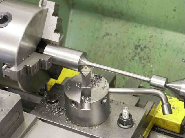
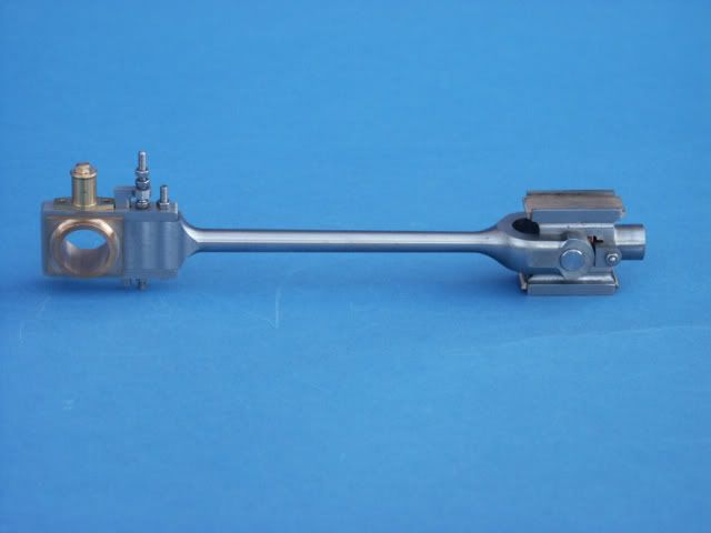
Stuart Turner Launch engine con rod.

Home Model Engine Machinist Forum

Help Support Home Model Engine Machinist Forum:

This site may earn a commission from merchant affiliate links, including eBay, Amazon, and others.

KBC

Junior Member
Joined
Feb 22, 2012
Messages
80
Reaction score
53
Hi,
This is my first posting on this forum although I have had many tips from reading members postings.
I am in need of a Stuart Turner Launch engine con rod casting does anybody have a spare that I could purchase.
As I was machining into the neck of the rod the tool dug into the cast gunmetal casting and it has ruined the casting.

I am about 75% completed and Stuart doesn't have any spares ( whats new ?? )
Any help would be appreciated.
Geo.
 
Welcome Geo-

I started looking at all the various Stuart engine types the other day, trying to figure out how many different models were made.
The more I looked, the more types I found (some apparently discontinued).

Here is my list (this list may or may not be accurate).

So what type of Launch engine do you have?
Bore, stroke, compound, or simple?

------------------------------------------------------------------------------
Vertical A-Frame style Engines
(all with cylindrical crosshead and Stephenson's reverse gear or reverse gear option)

Cygnet
Vertical A-Frame Single
bore: 2.25", stroke: 2"
(Discontinued?)

Swan
Vertical A-frame Twin (looks like two Cygnets)
bore: 2.25", stroke: 2"
(Discontinued?)

No. 5A
Vertical A-Frame Single (looks like a Cygnet, but without the accessories)
bore: 2.25", stroke: 2"
[ame]http://www.youtube.com/watch?v=eJXxFX9GLyg[/ame]
(Discontinued?)

No. 4
Vertical A-Frame Single
bore: 1.5", stroke: 1.25", flywheel: 5"
http://www.stuartmodels.com/inprod_det.cfm/section/casting/mod_id/65

No. 7A
Vertical A-Frame Single
bore: 1", stroke: 1", flywheel: 3.5"
http://www.stuartmodels.com/inprod_det.cfm/section/casting/mod_id/50

No. 10V
Vertical A-Frame Single
bore; 0.75", stroke: 0.75", flywheel: 3"
(Discontinued?)

No. D10
Vertical A-Frame Twin Engine (Looks like a slightly smaller twin version of the 7A)
bore: 0.75", stroke: 0.75", flywheel: 1.625"
http://www.stuartmodels.com/inprod_det.cfm/section/machined/mod_id/27

------------------------------------------------------------------------------
Horizontal Engines

Mill Engine (Horizontal Single)
Loco crosshead, valve on side of cylinder, long stroke.
bore: 0.625", stroke: 1.25"
(Discontinued?)

Victoria (Horizontal Single)
Loco crosshead, valve on top of cyinder, long stroke.
bore: 1", stroke: 2"
http://www.stuartmodels.com/inprod_det.cfm/section/casting/mod_id/46

Victorian Twin (Horizontal Twin)
Loco crosshead, valve on top of cyinder, long stroke.
bore: 2x1", stroke: 2"
http://www.stuartmodels.com/inprod_det.cfm/section/casting/mod_id/47

No. 9 (Horizontal Single)
Slipper-type crosshead, valve on top of cylinder, short stroke.
bore: 1.5", stroke: 1.5", flywheel: 5.125"
http://www.stuartmodels.com/inprod_det.cfm/section/casting/mod_id/49

No. 8 (Horizontal Single)
Cylindrical crosshead, valve on side of cylinder, short stroke.
bore: 1", stroke: 1"
http://www.stuartmodels.com/inprod_det.cfm/section/casting/mod_id/66

No. 10H (Horizontal Single)
Cylindrical crosshead, valve on side of cylinder, short stroke.
bore: 0.75", stroke: 0.75", flywheel: 3"
http://www.stuartmodels.com/inprod_det.cfm/section/machined/mod_id/28

Score (Horizontal Twin)
Looks like two No.10H's.
Cylindrical crosshead, valve on side of cylinder, short stroke.
bore: 2x0.75", stroke: 0.75", flywheel: 3"
http://www.stuartmodels.com/inprod_det.cfm/section/casting/mod_id/42

------------------------------------------------------------------------------
Open Column Marine Engines (all with Stephenson's reverse gear or option)

Twin Launch (Open Column Twin Launch - Single Expansion)
bore: 2x1", stroke: 1", flywheel: ?
(Discontinued?)

Twin Launch Compound (Open Column Twin Launch - Double Expansion)
bore: 0.75" and 1.25", stroke: 1", flywheel ?
(Discontinued?)

No. 3 (Open Column Twin Launch - Single Expansion)
http://www.stationroadsteam.co.uk/Stuart/No.3.htm
bore: 2x2.5" (single expansion configuration)
stroke: 1.5"
(Discontinued?)

No. 3 (Open Column Twin Launch - Double Expansion)
http://www.stationroadsteam.co.uk/Stuart/No.3.htm
bore: 1.5" and 2.25" (compound configuration)
stroke: 1.5"
(Discontinued?)

Triple-Expansion (Open Column Triple Launch - Triple Expansion)
Vertical Marine-Style Open-Column Engine
bores: 0.75", 1.25" and 1.75", stroke: 1", flywheel: 2.25"
http://www.stuartmodels.com/inprod_det.cfm/section/casting/mod_id/70

Double-Expansion (Open Column Twin Launch - Double Expansion)
While it does not appear on the regular Stuart website, a google search reveals a
No. 6A compound twin marine engine, bores 2.5" and 4", stroke 3".
http://www.stuartmodels.com/inprod_det.cfm/section/casting/mod_id/57
I don't know if this engine is still available or not.

------------------------------------------------------------------------------
Beam Engines

Beam Engine
bore: 1", stroke: 2"
http://www.stuartmodels.com/inprod_det.cfm/section/casting/mod_id/43

Half-Beam Engine
bore: 1", stroke: 2"
http://www.stuartmodels.com/inprod_det.cfm/section/casting/mod_id/45

Major Beam Engine
bore: 1.75", stroke: 3.75"
(This was the best looking of the beam engines.)
(Discontinued?)

------------------------------------------------------------------------------
Oscillator Type Engines
Stuart has a variety of small oscillators (not listed here).

------------------------------------------------------------------------------
Special Type Engines

No.1
A vertical, single-cylinder, open-column engine.
In my opinion, this was the best looking Stuart ever made.
(Discontinued?)
[ame]http://www.youtube.com/watch?v=mD4ci-GHrPo[/ame]

Sirius (Vertical Twin, Single-Acting, Enclosed)
bore: 1", stroke: 1"
This is a slick little Westinghouse-style engine, used to power a small genset during the war.
http://www.stationroadsteam.co.uk/Stuart/sirius.htm

Sun (Vertical Twin, Single-Acting, Enclosed)
bore: 0.75", stroke: 0.75"

James Coombes (Table Engine)
http://www.stuartmodels.com/inprod_det.cfm/section/casting/mod_id/48

800 Gas Engine
Real (Inverted Engine) (Inverted is my term)
4-leg open column engine, top mounted flywheel
bore: 1", stroke: 2"

Williams (Inverted Engine) (Inverted is my term)
Single column engine, top mounted flywheel
bore: 0.625", stroke: 1.125"

------------------------------------------------------------------------------


welcome George nice to see you posting on hear,

Peter
 
UNIcastings,
The engine is the Twin Launch engine of 1'Bore x 7/8" stroke which has the same con rods as the Compound engine I chose the Non condensing engine as it's self starting as the Compound isn't,
so a con rod from either would do.
I may have to fabricate one if non are available.
I have refrained from posting the engine progress as there has been postings before, however here are some pics of the modifications that I have made.
The bed plate on the engine is used as the bottom half of the 3- main bearings which I don't like so I used the top half of the bearing and made the bottom half from a piece of Cast Gunmetal, this means that the 5- columns have to be lengthened.

The eccentric sheaves are different as I have left flanges to give the eccentrics a bigger bearing surface.

The main shaft webs have been made like the balanced type webs.

To you and Peter thanks for the welcome.
A little about myself, retired design engineer , trained as a Millwright , never worked as a Journey man, straight into D.O. spent 20 years on design of textile machinery, 20 years on office and building refurb.
Never had the chance to do much machining but since retiral I have made all of the Stuart 10 engines and pumps and have experimented with Flash Steam in a model R.C. boat 42" long and have achieved 40 m.p.h with it, at present it's on the shelf as it's becoming too dangerous.
Limited machinery, lathe and mill drill.

Geo.

Eccentrics on shaft..JPG


Main shaft :5.JPG
 
I don't know how badly you mangled the conrod, but you might try bending it back into shape and repairing it. I had an eccentric strap to the Stuart triple I'm currently making get torn free from the clamping fixture as I was performing final profiling, and I thought the part was beyond hope. I was able to bend it back into shape and complete the profiling. the finished part came out as perfectly as the others. Gunmetal bends very easily. If too much material got removed, you could silver solder a patch in place which when machined will probably become invisible.

I just checked Stuart's website. Though they have a number of spare parts for the two twin marine engines (which share most parts), they don't appear to have any spare conrods. Be aware that even if they did have spare parts, depending on the vintage of your casting kit, it is possible current spares may not fit your engine anyway. I recently acquired a 1960's twin launch casting kit, and there are a number of parts that are quite different to that of the twin launches sold up to about 6 months ago. Most of Stuart’s engines have changed (including dimensions) over the years.

If your conrod castings are the same as those that came with my twin kit, I can certainly understand how you damaged one, as they sure didn’t provide much in the way of holding spots to what is already a rather dainty casting that needs a lot of different machining. Having made the equally dainty conrods for my triple out of SS, I was very thankful to have started from bar stock which allowed me to machine from one end to the other in one clamping operation to virtually eliminate the risk of bending and so I didn’t lose any alignment or precision. I’m going to have to devise another method when it comes to the twin’s conrods.

Robin
 
Many thanks for your replies,
At last I have found a site where machinist can pass on their experiences to other members benefit.
I had already started thinking about a steel rod with bronze bearings which is now the road that I will go.
Some years ago I built a Reeves Borderer from scratch using bar stock , a lump of square cast iron window sash weight from a scrap yard( not to be recommended as they are very poor material ) and in this engine I made steel rods with bronze bearings.

So now armed with pics of "HOW TO" I shall keep you posted on my progress.

Pics of Reeeves Borderer.

Geo.


P:VALVE ENGINE 4.JPG


P: VALVE ENGINE 2.JPG


P:VALVE ENGINE 1.JPG
 
Robin,
The castings for this engine are very poor with quite a few blow holes in the castings.
As you can see from the pic of the reversing eccentric there is a small hole but not enough to worry about.
They could have left spigots on the castings as they do with the D10 & 10V and let you get a grip of them in the chuck.
The damage to the conrod was when I was coming back down to the bearing end and the tool dug in and the lot came out of the chuck.

However with the help of Jason's pics I have started the first new one in B.M.S.( swarf every where ) I'm good at making swarf. and the bearing will be in Phos Bronze.

George.


Con rod Damage:1.JPG


Eccentric with blow  hole.JPG
 
Hi George,
Nice to see you on here, this forum is streets ahead of the one we use to
belong to, with very knowledgeable and helpful engineers.

With regard to your eccentrics I had a similar problem on my launch engine so I machined mine from steel.

Mick


Jasonb said:
You should be able to make one from steel with bronze big end if you don't have any luck sourcing a casting, this will give you an idea of how to go about it.

http://modelengines.info/goldeng/const/rod.html

And this is a good guide to doing the cast one

http://compound.modelengines.info/rods.html

J

Hi Guys,
Thanks for the input from Jason and others on holding and machining the con-rod from steel, here are pics of the nearly finished rod, just need to machine the bearing down to size.

Jason your pics of making your rods were very helpful on how to hold and machine .
Here is a pic of the first con-rod with gun metal bearing block which I was pleased with the result.
However I don't know whether I should post this here or in the BLUNDER SECTION

Does anybody see the Boo-Boo I must say that I feel a right EEJIT the cross head yoke is 90deg out from the rotation of the bearing.

Never mind I at least now know how to make them and hold them, back to the work shop.

George.


New conrod:1.JPG


New conrod:2.JPG
 
Never mind I at least now know how to make them and hold them, back to the work shop.

Oops. Easy done.
May I venture to suggest the shape at the little end could be a bit better too. It looks as if it is a bit thin where it forks.
In turning I think the tapered shank should run into a taper or a hemisphere and then a short cylindrical bit, so that when you put flats on the sides the little end looks a bit like a U bent up from flat bar, avoiding steps in the section. Difficult to describe, but a look at some 12"/foot engines such as at http://www.prestonservices.co.uk/marine.htm will show you the idea.
 
Charles.
Thanks for your input, there is however plenty of metal at the yoke as it more or less to size from Stuarts drawing and remember the original was cast gunmetal where this one is in steel, I agree with you that the bottom of the eye could be a bit thicker for appearance so I will check it out against the cross head slide.
I think I know what you are getting at regarding the bottom end of the rod but as the bearing is 3/8" thk thro' and the main body of the bearing finishes at 1/4 " as does the bottom dia of the rod flats can't be shown unless the bottom of the rod was left at 5/16" then flats would be shown.
I think that's what you are getting at.
Nearly completed the 2- new rods.
George.
 
Charles,
It,s made to the drawing.
George.
 
I think what makes it look a bit wrong is the cylindrical part at the end of the tapered shaft. This should really transition with a concave part then a convex outer edge. This is best done with a ball turning attachment a bit like this one that is part way through being roughed out.

PICT0053.jpg


You then mill flats on either side so that when the fork is milled out the outer profile follows that of the curved bottom of the fork. A bit of rounding around the bosses helps as well and then you end up with something like this.

PICT0109.jpg


Jason

PS Those photos in the earlier links are not my work.
 
Yes Guys,
I'm with you now, but don't forget the rod wasn't completed, it was after I noticed that the eye was 90 deg out that I abandoned completion so I will have a good look at what you are saying when I make the 2- new ones.
At present the rods are in the same condition as Jason's pic with the job in the lathe and the tool at the thick end.
Thanks for your interest.
George.
 
At Last I am able to thank all of you guys for the info on machining the con rods from steel with gun metal bearings.
I was side tracked in completing a D10 engine to install in my steam tug CERVIA which is now running so I was able to get back to the launch engine which is now about 90% completed with the pipe work still to do.

I have made one or two mods to the engine which I think are for the better so here are some pics.

Pic No --1
Making the eccentric sheaves without the central raised guide to give a better bearing surface.

No2--
Bearing blocks from Gunmetal instead of the method of machining a groove to act as the bottom half of the bearing.

No--3
New Con rods and eccentrics fitted.

No--4
Weigh shaft, eccentrics and reverse lever fitted.

No--5.
O/all view of engine with pipe work still to be made and fitted.

So thanks again your help has been very much appreciated and when I have it up and steaming I will let you know.

George.

Eccentrics on shaft..jpg


Main shaft :7.jpg


Reverse gear:5.jpg


S:T reverse:2.jpg


S:T reverse:3.jpg
 
Nice finish George. Looking forward to see it run.

Vince
 
  • Like
Reactions: KBC
Looking good, but you can't say things like finishing the D10 for my steam tug without sharing photos of that as well! ;)
 
Looking good, but you can't say things like finishing the D10 for my steam tug without sharing photos of that as well! ;)

Hi Brian,
As requested here are some pics of the D10, I won't bore you with all off the machining process as it has been done on this forum before.
My steam tug is CERVIA at 3/8" to 1ft .
42" long x 10" beam x all up weight of 35 lbs.
It's 40 years old and originally powered by electric motor, lay up in my loft for 25 years and brought down when I retired 13 years ago and converted to steam.
Original engine was a !0 v but being single cylinder double acting wasn't self starting or reversible, after many years of Heath Robinson ideas using slip eccentric I decided on the D10.

I haven't quite figure out how to print in between pics so I am afraid you will have to figure them out.
The Flywheel has a taper sleeve on it as I have found by experience that a 5 BA grub screw as per the drawing is hopeless so it now locks on by the brass nut on the split collet sleeve., the large black rubber spacer is from the rubber heel of an old shoe.
The pump is made from the scrap box and is driven by a Scotch crank with holes at different pitches to allow adjustment.
The weigh shaft has a lever with holes for a servo to operate, I had to upgrade the servo to 14 kg pull to effectively operate the reversing gear.

Lastly the D10 next to the Launch engine.

I have built several D10's and10V's, several Stuart steam boiler feed pumps but my real passion is Flash Steam which I have a boat that will do 40 M.P.H. and is self built based on R.Kirtley's current Hydro world record boat.
My Steamer being radio controlled is a bit dangerous as it gets faster so it's in dry dock at present until I figure what I am going to do with it.

I hope that this is of interest to you.

George.

Cervia:1:5.jpg


Drive disc:2.jpg


New shaft:2.jpg


Assembled pump:2.jpg


Assembled pump:3.jpg


Engine srvo arm.jpg


D10 Flywheel:6.jpg


Servo arm.jpg


D10&Launch engines:2.jpg
 
Back
Top