Small V8

Home Model Engine Machinist Forum

Help Support Home Model Engine Machinist Forum:

This site may earn a commission from merchant affiliate links, including eBay, Amazon, and others.
Hello All!

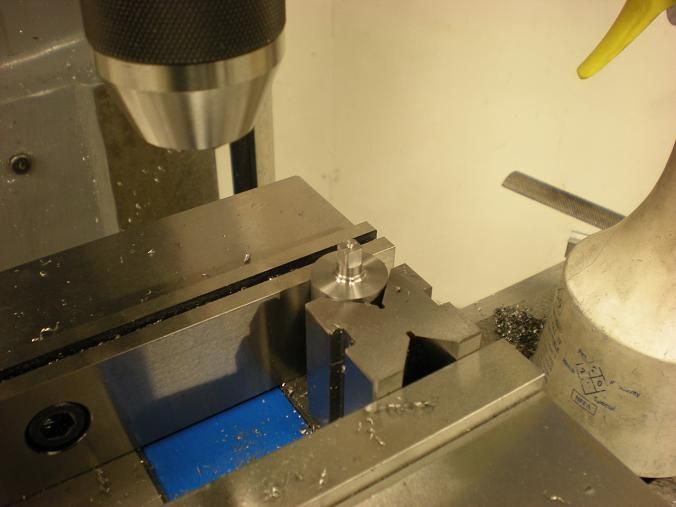
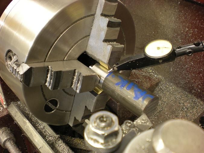
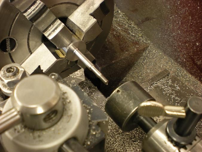
Made a bit more progress today. Chucked up the rear pieces and started to finish them up. I used my "bat wings" (brass inserts) on the jaws so i wouldn't damage the finish. Indicated to less than .001

DSCN0534s.jpg


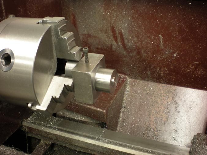
I turned the shaft down to about .010 over size and then got the tail shaft ready for threads.
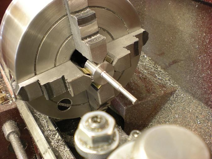
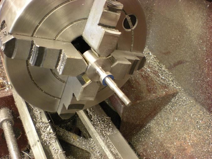
DSCN0536s.jpg


Ran the threads on.

DSCN0538s.jpg


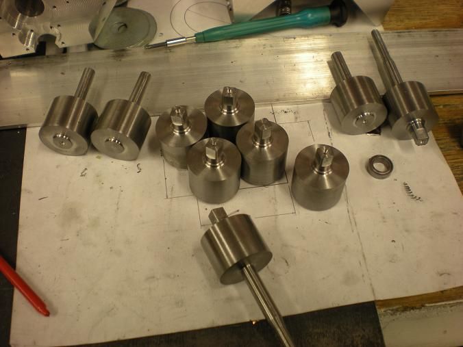
Finished the shaft to .0005 - .001 oversize and then i like to bring the shaft to size using some 320 sand paper. This way I can work the taper out if there is any and i can usually hit my number within a few tenths.

DSCN0540s.jpg


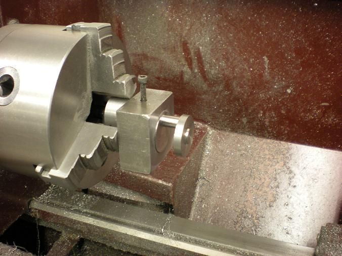
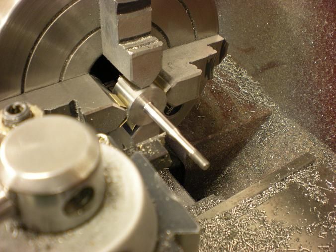
Then I put the taper on last.

DSCN0541s.jpg


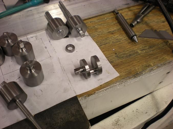
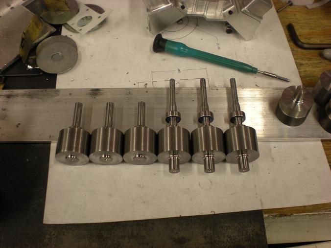
Thats about all until I get my hands on a 5/16 collet.

DSCN0546s.jpg
 
Well the tractor and loader did most of the work and I got up at 6 this morning so I could have a couple of hours in the shop. Trying to get the Siamese twin finished.
 
deere_x475guy said:
Well the tractor and loader did most of the work and I got up at 6 this morning so I could have a couple of hours in the shop. Trying to get the Siamese twin finished.

Just be careful you don't smash yourself up again. Don't need more surgery.

Screw the twin, want me to send over some V8 plans? Hahhahah!!

How goes the coating and anodizing? Last I saw you were getting some real nice parts.
 
Yea, I am still getting on an average 2 rhizotomys a year. Its been 4 months since the last one and I am still doing well.

I am now using a 20 amp 24 volt power supply I picked up cheap on Craig's list and I bought a PWM to control the out put. It works great and I bet it would work well with just a computer power supply. I didn't post anything about it yet. I wanted to give it a work out first. I will probably update the thread later this week.

I would love to see the plans.... :bow:
 
Looks great Steve, but am I missing some type of follower or steady rest for the crank end pieces? With that much overhang, your either compensating ,or fighting, a bunch of deflection I would think.
 
Lakc said:
Looks great Steve, but am I missing some type of follower or steady rest for the crank end pieces? With that much overhang, your either compensating ,or fighting, a bunch of deflection I would think.

That's why I finish with sand paper. I was getting about 4 - 6 tenths taper so I just polished the taper out with paper. Takes only a minute or 2 and I can typically get a short shaft like that to within 2 tenths all the way across.
 
stevehuckss396 said:
That's why I finish with sand paper. I was getting about 4 - 6 tenths taper so I just polished the taper out with paper. Takes only a minute or 2 and I can typically get a short shaft like that to within 2 tenths all the way across.
Sounds like you won that fight then. ;D
 
Hi Steve, this method of manufacturing the crankshaft I have never seen before. It is of great interest to me. I tried to offset turn my crank on the same type of lathe that you have pictured and basically had to run for cover due to the chatter produced. I had to bite the bullet and purchase a larger machine for the rigidity. I am excited to see how you'r method works and may adapt the same technique. some time ago there was a post on here by Bogstandard relating to the performance of these smaller machines which I was at first skeptical but now totally agree. have you made any modifications to you'r lathe to enhance the performance, particularity parting off on diameter above
1 1/4"?. I have found brass ali and cast iron are fine, it is mainly 4140 and 4340 steel to be difficult. ??? ??? ??? Very nice work by the way, I enjoy watching this post.

Regards Barry.
 

Looking good Steve,

I really enjoy following along.
 
Following this great building with increasing interest Steve! I like the way you are trying the 2 crankshaft methods. I am very keen to hear how the 2 types come out, as the one-piece crankshaft has always been the part that seems the hardest in an engine like this. Particularly the fact that it will enable the use of ball bearings in the mains, I really hope the built-up crank works. I could definitely see myself going for a set of your plans. Keep up the excellent engineering and experimentation!
 
rcfreak177 said:
have you made any modifications to you'r lathe to enhance the performance, particularity parting off on diameter above
1 1/4"?. I have found brass ali and cast iron are fine, it is mainly 4140 and 4340 steel to be difficult. ??? ??? ??? Very nice work by the way, I enjoy watching this post.

Hi Berry

The lathe is as "out of the box" except for the QC tool post. and a DRO.
I try not to have to part off large stock. If i tried to part off 4340 it would probibly tip over.
 
LongRat said:
Following this great building with increasing interest Steve! I like the way you are trying the 2 crankshaft methods. I am very keen to hear how the 2 types come out, as the one-piece crankshaft has always been the part that seems the hardest in an engine like this. Particularly the fact that it will enable the use of ball bearings in the mains, I really hope the built-up crank works. I could definitely see myself going for a set of your plans. Keep up the excellent engineering and experimentation!

Thank you LongRat. We will keep on trucking.

 
Hi Steve

I am deeply interested in your version of building a multiple piece crankshaft too.

Just being in the end of the design phase for my next 2 cylinder IC engine I have to decide about my crankshaft layout soon.

And as I have to do all the turning jobs on this little “living room toy” lathe here (….ha ha ha….)


PD_360_FU_100.jpg


chatter and minor rigidity while extreme offset turning is always a serious problem to me too.

By the way, I have made very positive experience with ETG100 for all engine parts with higher strength demands, made the last crankshaft from this special steel too. But I don’t know if the name ETG is common for this kind of material in England and the USA?

If you are interested please have a look at this link, it’s written in English:

http://www.vanleeuwenbuizen.com/media/44357/73100-180808.pdf

ETG is a sort of free cutting steel, but it is twice as strong (tensile strength 1100 N/mm2) as the normal free cutting grades. In addition it is stress relieved, so complex parts don’t tend to get distortions so fast. And it’s most suitable for hardening with a propane flame, I made some special ore unusual milling tools from ETG over the last years and they all work fine.

Steve, I’m looking forward your ongoing report.

Achim
 
Finally made some progress with the crankshaft. Over the last day or two I managed to make the fixture to hold the pieces for turning. It's an ugly bugger but I did make a test piece and it works very well.


The first thing I did was to mill the square ends on the pieces that require them.

DSCN0609s.jpg


DSCN0606s.jpg


The pieces are then put into the fixture and the turning begins.

DSCN0610s.jpg


DSCN0613s.jpg


One down and eleven to go!!!

DSCN0615s.jpg


Cheers!

 
If you pull this off, Steve, you are a much better machinist than I will ever be! Of course, maybe you already knew that! :big: :bow:
 
cfellows said:
If you pull this off, Steve, you are a much better machinist than I will ever be! Of course, maybe you already knew that! :big: :bow:

Yeah right!! I have seen some of your work. If I pull this off you should have no problem doing one.

Just for the heck of it. What part of this do you think you can't do. I'm only asking because I was hoping to make this easy enough where people with less than "master machinest" skill level could make a V8. I admit that the 4 pieces is more work but I would hope the pieces are easier than making a one piece.

I ask this question to everyone who looks at this thread and not just Mr. Fellows.

 
Hi Steve,
Here's my 2 cents worth. I would say that making a multi piece crank like you're making would be easier for an average builder than making a one piece crank. That being said, the problem I see is holding the accuracy of the locator hole so that when the crank is assembled it will be concentric throughout. If the squares and pockets aren't within very close limits the crank won't be accurate and I don't know how much rigidity it will have.
It's good that you're trying this out because it will prove out the feasibility of this type of construction. If you have good results with it (and I hope you do) then it might tempt others to build a multi cylinder engine of their own.
Hopefully you'll have a couple of the cranks built in time for the Zanesville show. I would like to see one of them.
George
 
Steve, George has voiced the concerns that I would have. I, personally, have a hard time getting close fits with round stock going into holes, let alone square pegs going into square holes.

However, since each joint will be supported by a ball race, if you get a reasonably close fit between the square peg and square hole, rigidity shouldn't be an issue. By the way, how are you going to make the square holes? Doesn't look like you have enough room between the webs to use a broach... they're kind of long.

Chuck
 

Latest posts

Back
Top