That is some very nice work Steve!
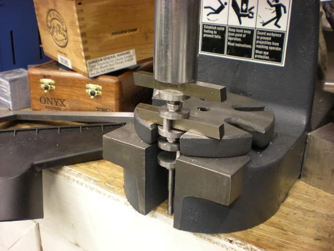
cfellows: If I were to attempt a built-up crank I'd probably machine the pegs & holes with some small clearance then machine a jig of main journals from a substantial solid to hold all the pieces concentric then silver solder the assembly in one.
cfellows: If I were to attempt a built-up crank I'd probably machine the pegs & holes with some small clearance then machine a jig of main journals from a substantial solid to hold all the pieces concentric then silver solder the assembly in one.

")