El Gringo--I decided to use a 3/16" crank because I already had some 3/16" cold rolled steel and I had to buy bearings anyways.

Senft "Poppin" engine
- Thread starter Brian Rupnow
- Start date


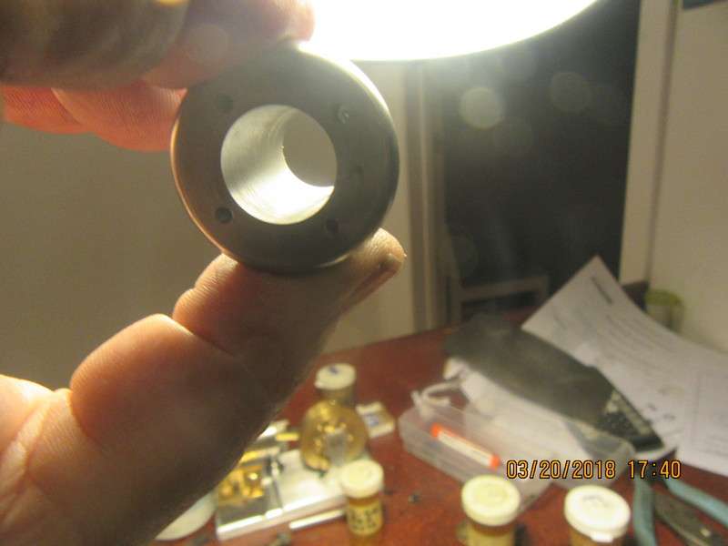
Oh wow--Christmas just came at my house!!! The laps that I ordered the other day came in just now. No more screwing around with home made laps. This is very timely, because now I can finish lapping the Poppin cylinder before I make the graphite piston.
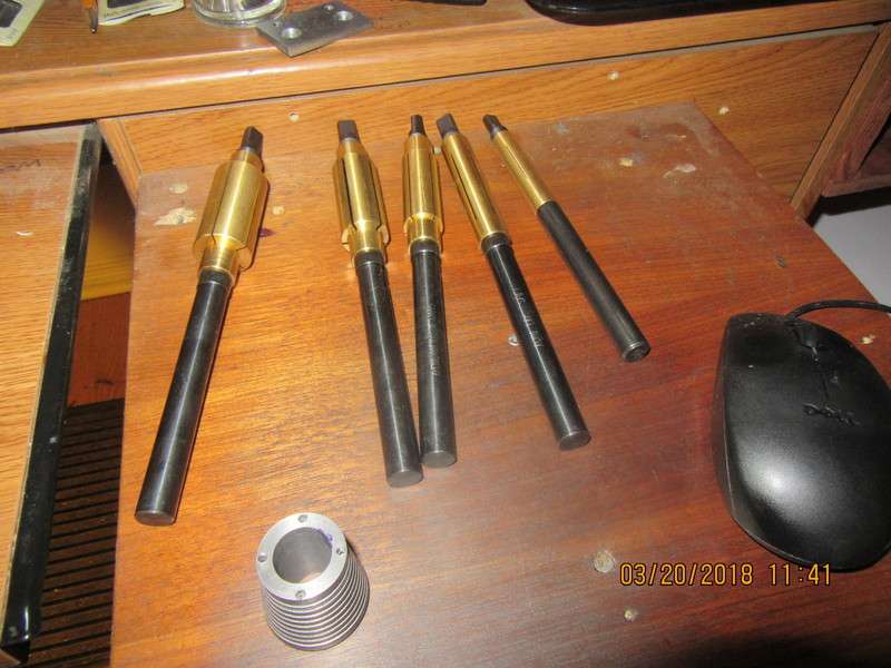


Oh wow--Christmas just came at my house!!! The laps that I ordered the other day came in just now. No more screwing around with home made laps. This is very timely, because now I can finish lapping the Poppin cylinder before I make the graphite piston.
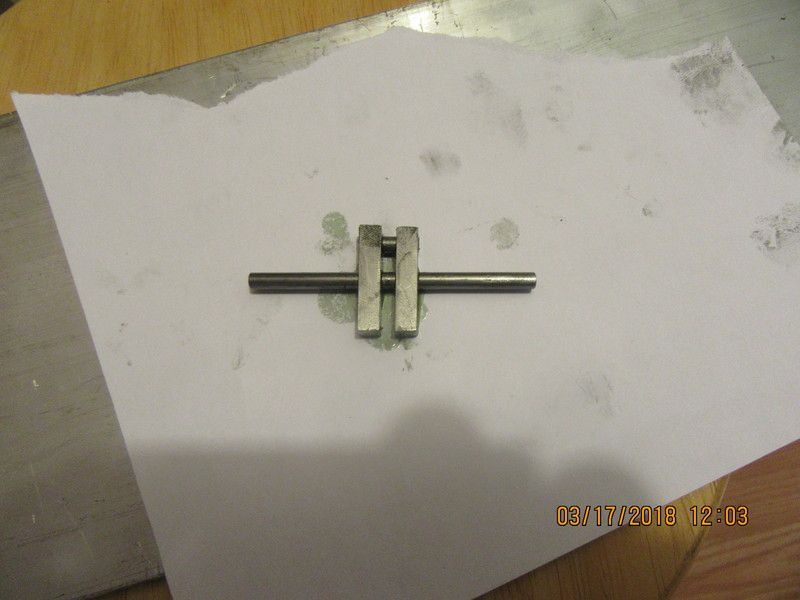
So, here we have crankshaft phase-1. Everything is cut to length and Loctited together. The shafts are not "press fit" into the square bars. They are a sliding fit. After 24 hours set-up time I will and pin all the joints with 1/16" dowels (Loctited into place), then wait another 24 hours and saw out the center bit.
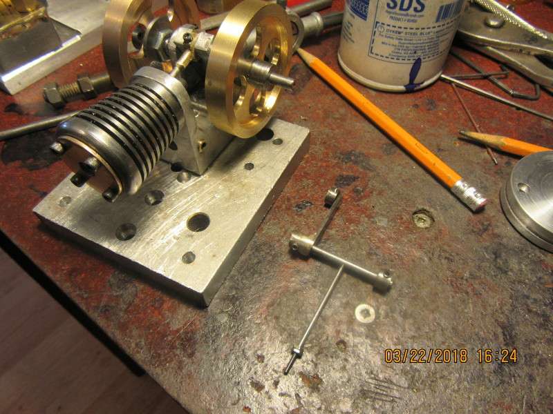
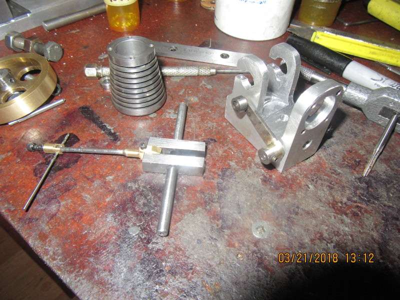
I bought a new #2-56 die today to thread the ends of the cross shaft that operates the valve. I have no idea what happened, but after threading down to the shoulder of the shaft and then backing off (by hand), the diameter of the shaft was decreased but no threads were on it. Very puzzling. Then I ran a #2-56 bolt thru the die, and it matched the threads just fine. Then I ran a #2-56 nut down the same bolt and it threaded okay. I had the shaft ends turned to .085". A mystery, and now I have to make a new shaft.
Enter your email address to join: