Senft "Poppin" engine

Home Model Engine Machinist Forum

Help Support Home Model Engine Machinist Forum:

This site may earn a commission from merchant affiliate links, including eBay, Amazon, and others.

Brian Rupnow

Design Engineer
Project of the Month Winner
Joined
May 23, 2008
Messages
14,969
Reaction score
8,247
Location
Barrie, Ontario, Canada
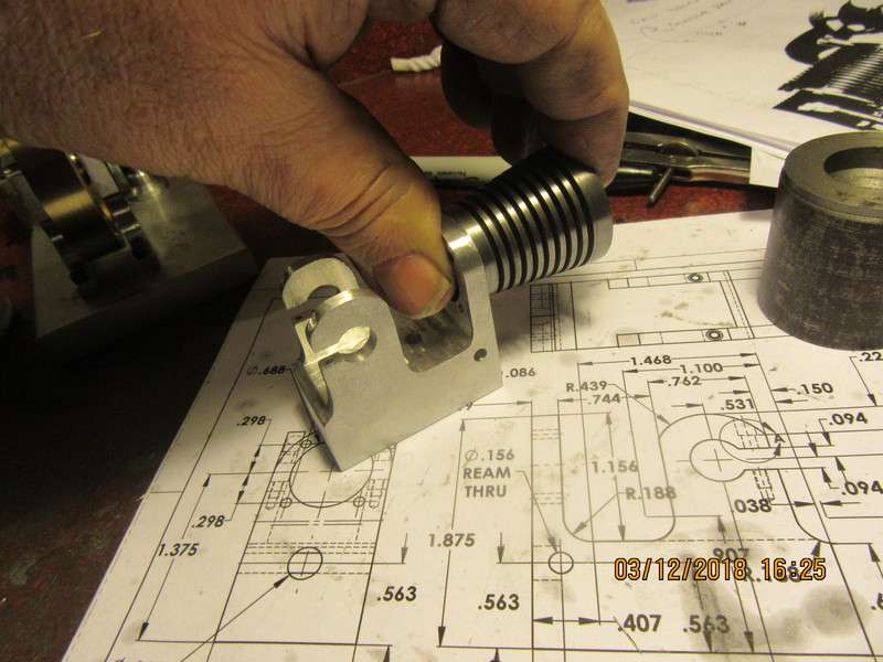
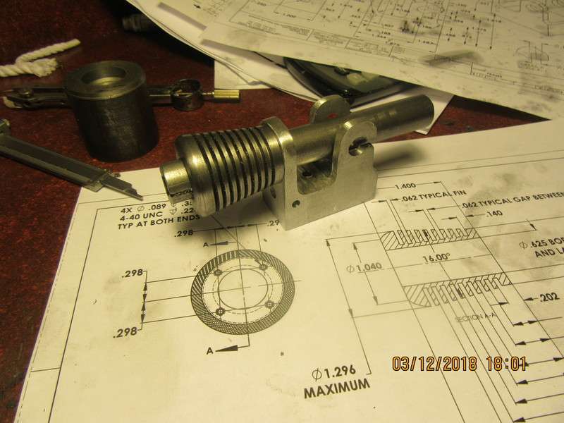
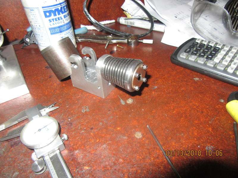
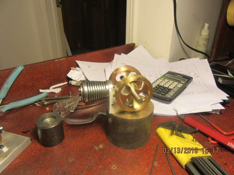
I just finished building the latest flame-licker engine designed by Jan Ridder, and my results were not what I hoped for. I did get it to run--long enough to get a video of it running.--But barely. I found it to be an easy build but a very temperamental and difficult engine to run. I don't think this was a result of my workmanship, as I have 25 other self built engines which all run quite well. It may have been my choice of 316 stainless steel for the cylinder. I tried it with a cast iron piston and valve and with a machinable graphite piston and valve, but the performance was no better with either material. I still want a flame licker engine which starts and runs repeatably, and after doing a fair bit of research have decided to build a "Poppin" engine from plans by Dr. J.R. Senft. I will attempt to post my progress and pictures of this engine as it is built.
HezjIm.jpg
 
nice looking model... I've been whittling on one of and on for a few months. I made the conrod of 2024 aluminum in order to eliminate the bearing in the big end, and not have to do the involved built up version as per drawings. The crank is one piece.

Ray M

P1000766.jpg


P1000767.jpg
 
If you really squint hard, and use your imagination, you can see the frame of this engine layed out on a piece of 2" x 1" aluminum bar.--Everything has to start somewhere.
wCfuvB.jpg
 
And considering that there were a couple more set-ups that I didn't photograph, that is a heck of a lot of work for something so small. I planned on making the cast iron cylinder today too, but I have to stop and grab some lunch (It's 3:00 PM here). I don't know if I'll do amymore today or not.
 
It would be nice to see an alternative design for the cylinder. I was looking at those plans not so long ago and I'll see how yours turns out first.
 
Here we have the sexy cylinder finished except for the tapped holes in each end. It is still mounted on the expanding mandrel in the picture.
0j1SeS.jpg
 
Today I made flywheels. I can't even imagine it, but that's a full 8 hours of my time. These flywheels are somewhat unique, because the hubs will be made as separate pieces. Maybe I'll make them tomorrow.
vVgxPj.jpg
 
Not a great deal done today, as I had a few hours of "real" work. I did however manage a pair of flywheel hubs and their accompanying nuts. (I cheated on the nuts---took a pair from my tool-chest and thinned them down on the lathe.) I have never seen flywheels made this way before, but it seems to work okay.
iBzHnn.jpg
 
I can't believe how fast you build...takes me months, at the least.
btw, will you be using cast iron piston/cyl as per plans?

I have about $100 invested in a stick of 1" diameter x 12" long machineable graphite that I bought to use on the Jan Ridders engine. I will be using it for the piston on this poppin.
 
Not a criticism, but an observation. Nothing shows up worse on a model engine than wobbling flywheels. When I make flywheels I generally leave a bit extra on the width and the diameter so that I can mount the finished flywheel on the correct size of arbor and give them a final "dressing" on the lathe to ensure that they are not wobbly as they revolve. Making flywheels with separate hubs that are not in any way "keyed" to the flywheel doubles the effort required to have the flywheels run true on the finished engine.
 

Latest posts

Back
Top