Senft "Poppin" engine

Home Model Engine Machinist Forum

Help Support Home Model Engine Machinist Forum:

This site may earn a commission from merchant affiliate links, including eBay, Amazon, and others.
Model aircraft guys use it Piano Wire 24g or beg an espresso machine filter holder spring clip from youre local coffee shop
Or been a tight wads I straightened a spring out and used that bit of wire
 
I worked in my office across town today, and managed to score a piece of .002" shim stock for the valve and a piece of 0.026" spring wire that should get the job done.
 
There is definitely a degree of "Hinky" to the valve mechanism on this engine. I have hidden one flywheel here to show the "hinkiness" a little better. The angular relationship between the lever with the roller on it and the small 1/16" diameter rod holding the 0.002" thick valve is adjustable. When the roller is fully "on the cam", the 1/16" diameter rod should be positioned so that the .002' thick valve just covers the hole in the cylinder head and overlaps the edge by about 0.015".--It doesn't in this picture--That was just me placing the 1/16" rod in a perfectly horizontal position when the roller was up on the cam. As you can see, the valve doesn't come close to covering the hole. I can sort out what the angle SHOULD be tomorrow. Then after establishing the correct angle, I have to establish exactly WHEN this event should take place in the cycle of the piston moving in the cylinder. Dr. Senft states that ideally, "Choose a direction of rotation and initially position the cam/flywheel on the crankshaft so that the valve closes the port when the piston has completed about 85% of it's outward motion, that is about 45 degrees before outer dead center."-I've never had so much fun with my clothes on!!
hPCFz3.jpg
 
I arose from my warm and comfy bed this morning and decided that this would be the day to build a proper engine base and start on a burner. Everything worked, everything fit, and now I'm off to a nearby coffee shop for some lunch. Goodwife has taken #2 son to #1 daughters house in Orangeville to repair a garage door, and I am left to amuse myself for the day. After lunch I will decide whether to finish the burner or set it aside and see if I can start the engine on a "borrowed burner" from another project.
jPRE6f.jpg
 
With no nuts on the cross shaft, I had to resort to a little "engineuity" to make a hub that will hold the piece of spring wire to spring-load the cross-shaft to close the valve. I just finished this part, and it's true--the smaller the part is, the more difficult it is to make.--I would have never made it as a watchmaker!!!
mZKh13.jpg
 
Enough for today. I have the .002" thick valve installed and have set the angular relationship between the valve roller arm and the 1/16" diameter rod that controls the valve. I have "timed" the engine correctly (I think). Senft says to choose a direction of rotation and set the timing so that the valve closes at about 45 degrees before the piston is at "outer dead center".--That confuses me. I have always worked in terms of "bottom dead center" and "top dead center". if anybody would like to clear that up for me, please do. The engine quacks like a duck if I spin the flywheel quickly by hand, so I think that is a good sign. It means that the vacuum in the cylinder as the piston moves towards bottom dead center is pulling the .002" thick valve totally closed.
 
That confuses me. I have always worked in terms of "bottom dead center" and "top dead center". if anybody would like to clear that up for me, please do.

'Outer' dead centre is just top dead centre but in a horizontal orientation there is no top or bottom as such. So it's outer (away from the crank) and inner (closer to the crank). Just a bit of outdated nomenclature.
 
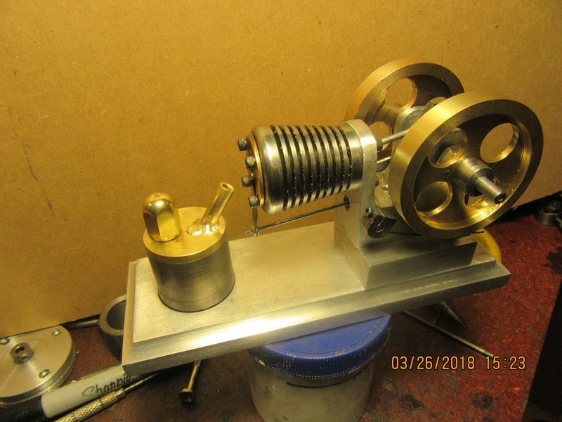
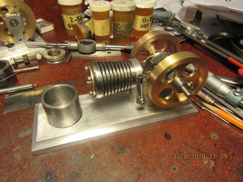
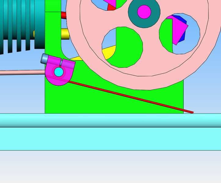
This morning I made a top for the alcohol burner but haven't soldered it on yet. I ordered a set of six 1/8" diameter wicks from Amazon, and I don't want to make the spout that holds the wick until I have the wicks in hand. I've also been looking at what happens with the engine timed the way I have it. When the cylinder is sticking out to the left, I want the flywheels to rotate clockwise. (This keeps from having to run my hand thru the flame after I've flicked the flywheel.) So--piston is at top dead center and valve is wide open. I start rotating the flywheel clockwise. Thru the first 45 degrees of rotation the valve stays open, sucking in flame. During the second 45 degrees of rotation the valve begins to close but hasn't fully closed yet. Thru the third 45 degrees of rotation the valve closes completely. During the last 45 degrees of rotation the valve remains closed and the piston reaches bottom dead center. In the next 45 degrees of rotation as the piston begins to be sucked back up towards top dead center, the valve stays closed for about the first 22.5 degrees, then begins to spring open and by the time it reaches 45 degrees the valve is fully open. The valve then remains open right on thru the top dead center piston position and doesn't close again until the whole cycle repeats itself.
 
I couldn't wait any longer. I had to see if this thing was going to work or not. I have the base cobbled together with a spacer between the base and the engine in order to get it high enough to use the burner from one of my other engines. I kept trying different timing settings until I worked all around the clock and came back to my original setting. I had to tweak the .002" valve a couple of times to ensure that it actually closed the hole in the cylinder head completely, and away it ran. I am feeling Oh so Good about this.
[ame]https://www.youtube.com/watch?v=RhrbGjgaaEk&feature=youtu.be[/ame]
 
During my build, someone suggested that I make two cylinder heads.--One as per the original plan, and one that looked like this. Same thickness, same bolt holes, a plain 1/4" hole in the center, and a 0.030" deep slot 0.020" wider than the 0.002" valve plate which seals and unseals the cylinder. This head would bolt right over top of the original cylinder head, and prevent the valve from falling to one side or the other and not covering the hole properly.--I see now that this is a very real possibility, as either the two #0-80 nuts don't hold the valve solidly enough to prevent it, or else the 1/16" diameter rod unscrews itself a bit from the cross shaft. I think this is probably a good idea, and will incorporate it into my build.
WPRN1v.jpg
 
Very nice Brian congrats.
They would be good on the desk top to run as I guess there wouldn't be much
odor ?
John
 
No odour, but there is an open flame. I really can't speak yet on the dependability or repeatability of this type of engine. I really don't know yet if once everything is sorted whether they start and run every time you want, or if there is a lot of fiddling to get them to run.---Brian
 
non sequitur; I wonder what two of those little guys would sound like would sound like running nose to nose on a common flame, one 180 deg out... might even be able to rig a common valve??
Ray M
 
Congratulations on a runner Brian.

I like the modified cylinder head idea and will be waiting and watching for it.

I also like the shape of the cylinder.

--ShopShoe
 
I had to go to court this morning for jury duty selection. Sat around for 3 hours with about 60 other people waiting and then we were told the case had been dismissed and we were all excused. I came home this afternoon, built a 1/2" spacer block to go between the engine and the base and mostly finished a burner for it. The burner needs a tiny bit of "fettling" but it was progress.
QsAFNq.jpg
 
When I put the 1/4" deep counterbore in the base to hold the alcohol burner, I put in a smaller diameter and 0.130 deep counterbore in the center to hold a rare earth magnet. The burner body is made from mild steel, and the magnet is epoxied into the small counterbore. This will keep the burner from moving around when I run the engine. I have also given a bit more thought to the double cylinder head to guide the .002" valve. Since the valve only needs guidance in one plane, I may just make a new thicker cylinder head with the valve groove cut into it. The current cylinder head is 1/16" thick. If I made a new one 1/8" thick this would allow a 1/16" deep groove, which would be sufficient to do what I want.
5mJD0z.jpg

oemDRD.jpg
 
Back
Top