Senft "Poppin" engine

Home Model Engine Machinist Forum

Help Support Home Model Engine Machinist Forum:

This site may earn a commission from merchant affiliate links, including eBay, Amazon, and others.
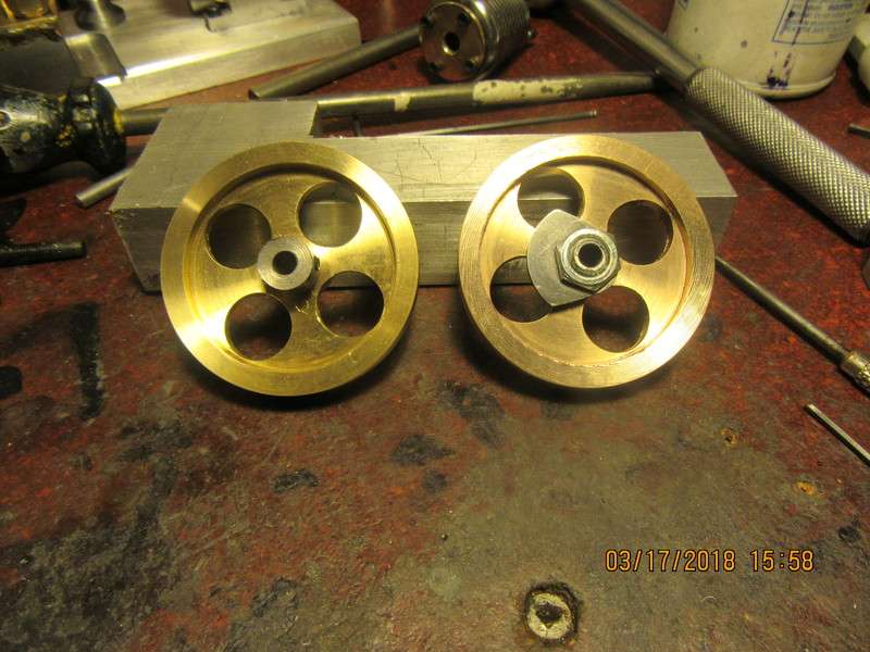
I can't swear to this, but my plan to address the flywheel issue is this. I will probably build the cam and cam washer and install them on one of the flywheels, then mix up a batch of J.B. Weld, coat the hubs with it, insert hubs into flywheels put cam and cam washer on one of the flywheels, then run the nuts down tight, and clean up any squeezed out mess. This should make each flywheel assembly a "composite unit". Then after 24 hours I will mount each assembly on a 3/16" arbor, tighten in place with the set-screws in the hubs, then true each flywheel individually. I am not concerned about balance here, just visual "flywheel wobble".
 
Was there flywheel run-out in the original Senft engines or did he use JB Weld to help with any fit problems? He mentions perfectly straight alignment using his built up crankshaft. I haven't used JB except in cases of a need for a filler or cosmetics when I didn't feel it critical to function or when I was too lazy to remake the part, maybe I'll be using it on these built up flywheels. I suppose making them as a monolithic unit would be a pain?

Ray M
 
Ray--In a perfect world, there would be no run out on the flywheels as designed. But the world isn't perfect place. My lathe has about .003 to .004 total indicated runout. I use a 3 jaw chuck, not collets. That means that every part that I turn on the lathe has the potential to be .0015 to .002" "out of center". If I mate two independently turned items, they have the potential of having no runout when assembled, or, if it's an unlucky day, they could be at the wrong end of both tolerances and be .003" to .004" out of center. The more turned parts I assemble, the greater the chances become of having enough runout to be visible. Also, the more faces and shoulders there are interacting with one and other, the more chances there are of visible "wobble" from side to side as they rotate. If I do use J B Weld, it wouldn't be to fill holes---It would simply serve to hold all of the assembled pieces together so that by fixturing on the center bore of the hub I can then do the final "trueing" of the assembly in one operation. One flywheel assembly has the flywheel, the hub, and the nut. The other flywheel assembly has the flywheel, the hub, the nut, the cam, and the cam washer (spacer) all assembled together.
 
My ball bearings came in yesterday. They are shielded bearings, not sealed. They should turn more freely than sealed bearings because the shields don't really touch the inner race. I may still have to wash the grease out of them in a solvent bath--will know about that later. Today I hope to make the crankshaft.
EhNGkA.jpg
 
So, here we have crankshaft phase-1. Everything is cut to length and Loctited together. The shafts are not "press fit" into the square bars. They are a sliding fit. After 24 hours set-up time I will and pin all the joints with 1/16" dowels (Loctited into place), then wait another 24 hours and saw out the center bit.
ZZEqNy.jpg
 
Thanks for the explanation Brian. My old 9" 1947 Southbend run about .0015 TIR +- (on a good day).
I'll shoot for a interference fit and see what happens...then I'll also see how true my one piece crankshaft is.
I wonder, if needed, I could reface the flywheels on the crank in situ?

Ray M
 
I decided not to use any J.B. Weld on the flywheel hubs. That would have been a bit too barbaric, even by my standards. I made the cam and cam spacer this afternoon, assembled everything and tightened it down as much as I dared, then set the flywheels up one at a time on a stub shaft with their hub assemblies in place and "trimmed" the outer diameter and the sides of each flywheel. It didn't take much, but it did take some. Now the flywheels don't visibly run out or wobble.
rFjQrE.jpg
 
This engine has a very interesting big end on the con rod. I haven't built one like this before. The red con-rod is silver soldered to the pale yellow part on the right hand end. The pale yellow part on the right is fastened to the pale blue part on the right with cyanoacrylate glue before any holes are made. Then both yellow and blue parts are tapped all the way through. A bolt is screwed through both parts and tightened. Then the hole is drilled and reamed for the crank journal on the split-line between the two pieces. Then the bolt is removed and the assembly is heated to release the crazy glue.
OBKHGE.jpg
 
This morning I got up and pinned the crankshaft. In a perfect world, I would have drilled the four holes undersize, then reamed them to 1/16" diameter.--In my world, the smallest drill I could find was 1/16" diameter, so that's what I used. In the foreground on top of the vice you can see the four "pins" prepared to go into the holes. The pins are flat on one end and a small taper ground on the other end, and about 1/4" longer than they need to be. First I tried the pins in the holes for fit and yes, they did fit perfectly. Then a small drop of Loctite on each hole, and the pins are inserted pointy side first and brought down until the top of the pin is flush with the side of the crank journal. In the second picture, the pins have been inserted and you can see the extra length extending below the underside of the crankshaft. If the four pins look a bit like welding rod, that's because they are. I can only buy 1/16" rod as "music wire" which is harder than the devil's horn to work with. However, somebody on the forum suggested 1/16" steel, copper coated welding rod, which is perfect for what I'm doing here.
L5zACN.jpg

Nc9n7A.jpg
 
Have been building a whole armada of tiny little pieces. Valve shaft bushings, valve cross shaft, valve lever arm. I still have half a dozen little pieces to make. I just realized that I polished the wrong side of the cylinder head and installed it backwards. The taper in the center should face into the cylinder, not outward as I have it. The crankshaft does indeed fit into the engine frame but barely. I had to order a 0-80 die and a 2-56 die, as I need them and don't have them. I downloaded these plans from the John-Tom site, and while the mechanical drawings are clear enough to see, the pictures are horrible. If anyone has built this engine, please post a nice clear picture of where the spring that holds the valve open goes. I can't tell from the stuff I downloaded. I think I will try to build the roller and roller carrier that goes on the end of the valve lever this afternoon and then call it a day.
31VtBY.jpg
 
I lapped the cylinder this afternoon, but wasn't terribly impressed with the resulting finish on the bore. I used a home made 5/8" lap that I had turned from a piece of aluminum. I had to take a step back and ask myself "Why am I still doing design work for money?"--It was supposed to be money designated for additional tooling in my machine shop. So---I just ordered a set of five barrel laps from KBC. I have one factory built lap that I bought a few years ago for 15/16" bores, and I was very pleased with the results it gave. I ordered a 1/2", a 5/8", a 3/4", a 7/8", and a 1". Sometimes you just gotta spend some money!!
 
Brian,
I admire your machining and design skills. Having said that, I have to ask: why do you not incorporate your own thoughts into other's designs? I.e. Mr. Senft's frame and con rod... alternatives are many. Is it because you honor the original designer by following his design to the tee?
I like to build my own designs, but of course every aspect is "borrowed" from the past. I don't consider that plagiarism.
Just curious.
Russ
 
RLukens--Take a look at my post count. Of the over 10,000 posts I have made over the last eight years, roughly a third of them are from my own original designs. However, I try not to claim other peoples designs as my original work. That's not as easy as you would think. There are only so many ways to make a cylinder--a crankshaft--a valve --a cam, you get the idea. If I seen something that wasn't right or looked like there was a better way of doing it, then yes, I would make the changes. From what I see of Mr. Senft's designs, there isn't a whole lot that needs changing. There are some ideas, such as his con-rod big end that are a bit different, and I like that. After building 25 engines over the last 8 years, I kind of like to do something a different way.
 
This morning I finished detailing the crankshaft. I used a pair of "flush cut" wire cutters to snip of the exposed ends of the 1/16" diameter cross pins , then used my monster stationary belt sander to clean up both sides. Before I cut the remaining piece of shaft out from between the rectangular bars, I chucked one end in the lathe and with my dial indicator on the unchucked end I measured 0.016" total runout. This didn't concern me too much, as these small shafts (3/16") are really flexible fliers. I took my rubber hammer and applied it to the shaft until the runout was only .002" total indicated runout. after I cut away the shaft between the rectangular crank throws, I measured again and it hadn't changed any. So---The crankshaft is finished.
oSidDc.jpg
 
Some very delicate work indeed going on here. This is the arm that operates the valve on the front of the cylinder. The arm is 1/16" thick material. The roller that you can see is 5/16" diameter. The axle inside that you can't see is .175" diameter with a .062 spigot that goes thru the arm.--And the roller has to turn freely after it is all assembled. The plans call for "peening" the head of the 1/16" part which extends thru the arm. I have never had a whole lot of luck with peening one part of an assembly while still leaving the other part free to rotate. I wimped out and silver soldered the projecting 1/16" spigot.---And my roller does spin freely!!
vgWul5.jpg
 
I'm having to retool my shop just to build this engine. So far I've had to order a #2-56 die, a 0-80 die and a tap, and I've found that nobody in Barrie carries 0-80 hex nuts. I'm working below my comfort level, size-wise, but so far it's coming together well.
 
Okay, I'd be the first one to agree, at first glance this looks uglier than original sin. Both brass pieces of the two piece big end have been carved out, one being silver soldered to a 3/32" diameter cold rolled steel rod (which I had to turn from 1/8" steel rod because I don't stock anything that small.) They are currently crazy-glued together and later today I will tap them while still crazy glued together, insert a full thread #2-56 bolt thru all, then drill and ream the hole for the con rod journal. Seems like a very strange way to make a con rod big end, and yet it doesn't require anymore pieces than a "normal" con rod big end does. It does cut down quite a lot on the "swing radius" of the con rod assembled on the crankshaft.--It is setting on a bigger aluminum block covered with saran wrap so that I don't glue it to the big aluminum block with a couple of 0.015" thick shims under them to maintain alignment .
pmOFSXNAj
 
Oh wow--Christmas just came at my house!!! The laps that I ordered the other day came in just now. No more screwing around with home made laps. This is very timely, because now I can finish lapping the Poppin cylinder before I make the graphite piston.
OoNNqR.jpg
 
"This didn't concern me too much, as these small shafts (3/16") are really flexible fliers".

My drawings show a 5/32 crankshaft main, I also had that size bearings on hand, although I thought that was quite small. I carved it out of 1144 stress-proof so maybe I'll get away with it...hopefully my flywheels are true and balanced enough not to flex the crank. I can see the headlines now, {cat is injured when chased by flywheel that broke off work hardened crankshaft while running engine at high RPM}:hDe:
 
The con rod big end does look okay now that it is finished and fitted. I have never made one this way before, so it was a new experience. If you really, really need radial clearance around the crankshaft, then this is probably a good idea. I don't particularly care for this method, as your options are very limited for any kind of adjustment. At any rate, it seems to work, and I've managed to do something "just a little different".
eNgH6M.jpg
 
Back
Top