Scale Model Clutch Pulley

Home Model Engine Machinist Forum

Help Support Home Model Engine Machinist Forum:

This site may earn a commission from merchant affiliate links, including eBay, Amazon, and others.

putputman

Senior Member
Joined
Nov 22, 2008
Messages
600
Reaction score
55
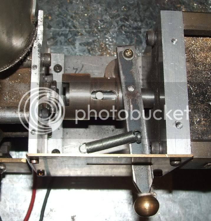
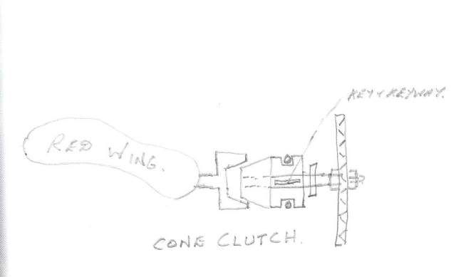
Has anyone out there built a clutch that fits scale models or know of plans available for a clutch. I know that DeBolt Machine sells a clutch, but I would rather make one if possible.

Would even consider a clutch that engages with the engine running but have to stop engine to disengage.
 
I guess it depends on the engine size,but a simple centrifugal clutch will engage at higher revs,and drop out when winding down to idle.In my rc car racing days,they used a pair of slotted ptfe shoes,with an o-ring as the spring element.They were supplied as a round disk,which the user cut in half,and shaped the shoes to his preferred size.The more removed,the higher the engaging revs required.
 
Putputman--Kind of a strange request---but--You could make one with the friction disc sliding on a square shaft, moved by a "picle-fork" lever. You could incorporate a compression spring to keep it engaged and use the lever to disengage it, or vice versa.
 
Bentprop, these are small scale model engines. I want to use it on hit & miss engines that are quite slow, 400-500 rpm. They are not throttle controlled so a centrifugal clutch probably would not work.

Brian, don't really know how strange the request is, but the reason for it is I would like to run a drag saw with a scale model Red Wing hit & miss engine. These engines sometimes need to get up to speed before you can put a load on them. That is the reason for a clutch.

I'm not clear on the clutch you described but it sounds very interesting. Is it possible that this "pickle fork" lever could somehow latch both open & closed? That would be the optimum clutch. One of the problems, of coarse, is it has to be somewhat scale to the engines, which makes it quite small.
 
Putputman

Does the clutch need to operate inline like an automobile or will it be used with a belt drive like a mill engine?

Jerry
 
Jerry, I will use it with a belt drive. It could be used on the driver or the driven pulley.
 
I have an idea that might work. What is the pulley diameter?

Jerry
 
Arv, the fellows who developed the Redwing and first sold the castings developed a clutch and sold drawings for the clutch. I believe the fellow from IA, who did the machine work for their first manual of build notes was the one who built the clutch. It had a handwheel that you could grab to push the clutch in or out of engagement. Perhaps the current Redwing vendors may know of this clutch drawing.

I saw the clutch in operation at NAMES back when it was still in the Yack Arena, so it has been a few years.

Regards,

Chuck
 
The drag saw will use bicycle chain. The driver will be about 9 teeth and the driven is a 52 tooth sprocket. I don't know off hand what the diameters are. They are up in the shop.
 
The easiest mechanical clutch that could be used is what is called a dog clutch and is used for things like disengaging leadscrews on a lathe, or anywhere a simple engage/disengage clutch is required, and can be used 'on the run'.

You don't have to use keys as shown in the sketch, you could use pegs into slightly larger holes. The more keys/pegs you put on makes the engagement much easier, as with just two, it can only engage every 180 degs, whereas with say 6, it will engage every 60 degs.

Bogs

dog clutch.jpg
 
Puttputtman.

My idea uses a plate attached to the engine shaft with friction material bonded to the face. Sheet cork might work for this. The output sheave floats on the shaft so the belt is not driven until the sheave is forced against the face of the drive plate. Bog's lever or Brian's pickle fork does the job. Some kind of over-center linkage could lock the clutch.
There will be considerable friction in the groove if you use this simple engagement mechanism. I could sketch up something using a ball thrust bearing if you think this might work. My drawing shows a flat pulley for flat belting but chain should be ok too.

Jerry


View attachment clutch.pdf
 
Here's one in real time - the table drive for my X2. The spring goes back behind the pivot point and acts 'over the centre to hold it either engaged or disengaged

clutch2.jpg
 
ppm,

How about a simple cone clutch ???

Cone.jpg


Hope this helps.

Best Regards
Bob
 
Jerry, I read your post last night, but I didn't notice the PFD file until this morning. I think that is what I am looking for.

If I can combine your design with the cone type clutch and use Tel's spring loaded mechanism It might work out. I will probably have to design it into the driven sprocket so I have enough room for all of that.

What would be a good readily available material to use for the friction surface. I'm thinking something along the lines of automobile brake shoe linings. Don't know if they are available in raw stock.
 
Here is a revised PDF with a cone clutch. Brake lining would be ideal but I doubt you will find suitable size. You might try cork sheet, like gasket material.

I also included a ball bearing pressure mechanism. I hope my drawing is understandable. This has the advantage of eliminating friction in the lever contact grooves because now the engagement plate does not rotate.

Jerry

View attachment clutch with bearing.pdf
 
Puttputtman

It just occurred to me that wood might be a usable and authentic friction material. I have seen wooden clutches on steam traction engines. I'm thinking smooth hardwood like maple would be a good choice.

No matter what material you use, clutch pressure could be problem. I doubt that just an over center spring will provide enough pressure. One advantage of a dog clutch is that it does not require much force to keep it engaged, but they produce considerable shock if applied under speed. Older Caterpillar motor graders (before about 1960) used dog clutches to engage blade positioning linkage. Lever kickback broke a lot of wrist before they finally went to hydraulics.

I think you will need some kind of knuckle linkage like you find on some bench clamps or vise grip pliers. A notched segment like on a johnson bar would work too.

A steep angle on the cone will reduce needed pressure.

Jerry
 
Jerry, have been studying your last PDF. I am wondering if it work work to bond in a lining made out of a hockey puck. That is hard vulcanized rubber. If it snapped in and engaged quite fast, there would be little slippage and the rubber would take the impact.

Daaaaang it is nice when people put there heads together. :big:
 
Ppm,

For a small clutch such as this, metal to metal may work just as well - just a thought. ???

Best Regards
Bob
 

Latest posts

Back
Top