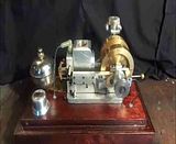
Hi Brian-- It looks good
as for the vibration the Wheel has nothing to do with the dampening
of the vibration.
the weight does it hall same thing when you bolt it to your workbench
the clamp does not damper the vibration but the weight of the bench does.
I think that if you mount the motor on 4 valve spring you will be able do cancel the vibration using different tension on the spring
I'm back to the build tomorrow check for pictures soon