Rupnow i.c. Engine with governor

Home Model Engine Machinist Forum

Help Support Home Model Engine Machinist Forum:

This site may earn a commission from merchant affiliate links, including eBay, Amazon, and others.
I can't believe it!! I only have one part left to make, and that's the latch for the exhaust valve lockout. It seems to me like I've been machining forever, but really its only been about a month. The spring that you see on the adjusting post with the knurled knob is probably not going to be the spring that gets used---Its just on there for the sake of taking the picture. I have also put up a picture of the other side of the engine, so you can see the nose of the pivot shaft sticking out from the sideplate. The lockout latch will fit onto the end of that rod. My 3D software informs me that there are 111 parts in this engine, not counting the fasteners. Tomorrow, or possibly even today, I will make that lockout lever and get the engine running in hit and miss mode ---I HOPE!!!!!

 
This is a short video showing the rotation of the cross shaft that operates the latch which holds the exhaust valve open. I have the latch up on my mill right now, and hope to finish it in the morning. Cross your fingers for me guys.--If I've lived right, I may have a hit and miss engine hitting and missing sometime tomorrow.---Brian
 
Those were purchased 5/8" brass balls that I robbed off one of my other governors. I don't want to buy more brass balls until I see what size is going to work satisfactorily.
 
Hi Brian,

Basis I got Webbie running tomorrow ,I try very hard not to build your current engine. Temptation
is too great. Most likely succumb.

Please post video when it is up and running.
 
Time for a break!! I had thought that perhaps the 5/8" balls I used for the governor flyballs might be too light, but I can put that one to bed. They are lots heavy enough. In fact, once that engine starts to fire, its almost impossible to keep them from flying out and engaging the lockout latch immediately. I am probably going to need a stronger spring on that springpost to counteract the "flying out" of the flyballs. I have had the engine running in hit and miss mode this morning, but not consistently enough to make a video. For you fellows wondering where to get brass balls, you can buy them from many online sources, you can make your own, or you can just use a 5/8" length of 5/8" diameter brass or steel rod. They don't have to be round. When I was making up the 3 arms that the governor balls attach to I had a brain wave and tapped them #5-40 and attached the balls with a counterbored socket head capscrew. It has to be counterbored, otherwise the head of the bolt will hit the flywheel on that side.
 
do you have another gear that would recuce the rpm the ball are going at
ek like a smaller gear on the crank and a bigger one on the governor
 
Am I the only one that all this brass ball talk is just killing?
 
do you have another gear that would recuce the rpm the ball are going at
ek like a smaller gear on the crank and a bigger one on the governor
No Luc--I want them to go that fast. The faster they go, the smaller they can be. Since this is a prototype, I wasn't sure that 5/8" brass balls would be heavy enough. Now I see that they are of sufficient size, in fact I could probably have gotten away with 1/2" diameter. You will see on engines where the flyballs are geared off the camshaft which runs at half the crankshaft speed, either the balls are much larger or they are geared up from the camshaft to rotate faster. The only real "work" they do is move the latch in and out of the exhaust valve lifter.
 
Okay--After a days playing in the garage trying to find the "sweet spot" for this hit and miss engine to settle in at, I've made a discovery. The "down force" on that center rod in the governor stempost must be pretty damn significant. It has worn a hole almost completely through the brass lever. Of course I've had the spring wound down real tight to keep the latch from making the engine go into its "miss" cycle too soon. This "downforce" is directly proportional to the weight of the brass balls and the speed at which they are turning. I meant to take a picture of the hole, but didn't notice that the camera was still in video mode, so we now have a little video of it. I may try running it without the brass balls, only with the weight of the lever arms themselves to see what effect that has.---Brian
 
--Its been a long and somewhat frustrating day. Probably the best thing to do is to silver solder a small ball bearing into the indentation in the brass lever. That would last for a hundred years. I may have to reduce the size of the brass balls from 5/8" to 1/2", or perhaps make them of a lighter material, i.e. aluminum, which should theoretically decrease the downforce on the rod by a factor of three. Today I was chasing other inconsistencies in the engine. Sometimes it starts and runs like gangbusters for as long as I want it to. Other times it doesn't want to start. That shouldn't happen. Unless something is changing, then the engine should start and run the same every time, no matter what. The only thing that should conceivably change is the temperature gradient, and even that shouldn't cause dramatic differences in the engine behaviour. I am lucky, in that the engine has really great compression and the bearings, gears, etcetera all seem to be doing their jobs remarkably well. ---Brian
 
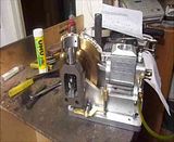
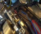
Good morning, my international engine building friends. After a long day spent in the shop yesterday with my new engine, its time for a report. Take heart--All of the major mechanical components work like a charm. That strange crankshaft/flywheel combination works very well. The single Viton ring give this thing all kinds of good compression. The valves seal very well, but I found that as usual I had both the intake and exhaust springs a bit too long and had to keep trimming them one coil at a time. You do this with the spring on the intake valve until, with the engine turning over at a good clip either by a belt driving motor or by your electric drill, you can see the exposed end of the valve start to "dance" as the suction from the intake stroke pulls it open. It won't move much, but it does have to move some.--otherwise your engine can't pull any air or fuel in for combustion. The exhaust valve spring has to be strong enough to hold the cam follower bearing in contact with the cam at all times, but not so strong that it causes undue wear on the face of the cam.--This is more a "seat of the pants" judgement call than anything. There are no clearance issues anywhere on the engine. The new ignition points mounting bracket that I had to design works well, and leaves the head of the shoulder bolt which holds the cam gear in place accessible so that it can be tightened adequately. I have been chasing a gremlin that seems to live in my carburetor, causing the engine to run fine for a while (you seen that in one of the videos I posted) and then without changing anything to not want to start at all. I assure you, this has nothing to do with the design of the engine, and everything to do with my carburetor building abilities. I did discover yesterday that the 5/8" diameter brass governor balls may be too heavy for the application. Don't rush out and buy any 5/8" brass balls at this stage of your build. I like the look of these balls "size wise" but they may end up being made of aluminum--I simply don't know yet. I have to do some more work on the governor mechanism. It works, but the steep angle that the latch mechanism sets on tends to wedge itself in place on the underside of the pushrod and not want to drop out when it should. I have a "fix" for that, and will be posting it this morning. Cheers, and keep up the great work I see being displayed in your posts.---Brian
 
This is what I mean by the angle of the "latch" being too steep. It swings up into place alright, actuated by the flyball governor, but then when the engine slows down and the latch should drop out and let the valve pushrod resume its normal operation, it can't because it is "trapped" in place by the force exerted by the exhaust valve spring.--Thus the engine just dies out and stops. I have a simple fix in mind, which won't change any of the parts you already have, but will require one more small part being built. I will be posting that part and an explanation of how it works later this morning.
 
I'm sure whatever your fix is will be elegant and simple Brian, I just wanted to let you know that on my Upshur I considered just this problem occuring, so I placed the 'latch' on the pushrod just short of full exhaust valve opening. This means each exhaust cycle in 'miss' mode still slightly opens the exhaust valve further and takes the weight of the spring off the latch. Then when it's ready it just falls out. Just some food for thought on the off chance you hadn't considered it.
 
There--That should do the trick!!! The latch is shown engaged in this picture. When the latch disengages it swings straight down, and there is no "notch" to hold it in place. The L shaped latch extension is bolted to the existing 3/16" square valve lifter rod with two #4-40 socket head capscrews. Fine tuning is accomplished by grinding the end of the horizontal latch rod until it disengages satisfactorily at the correct time.
 
Will the spring pressure from the exhaust valve not hold the arm in place causing it to not disengauge? unless the valve lift is higher than the arm then it will lift it off, or am I missing something?
 

Latest posts

Back
Top