Rockerblock I.C.--Something a little different-

Home Model Engine Machinist Forum

Help Support Home Model Engine Machinist Forum:

This site may earn a commission from merchant affiliate links, including eBay, Amazon, and others.
I disagree Niels.If Brian needs to be compact then single tapped holes thru
with short csk screws from each side are more compact and more pleasing
If the engine was a Victorian copy then nuts and washers/studs etc would
be more in keeping.If there is room then I would prefer button hex hd
rather than csk.Just me. Regards barry
 
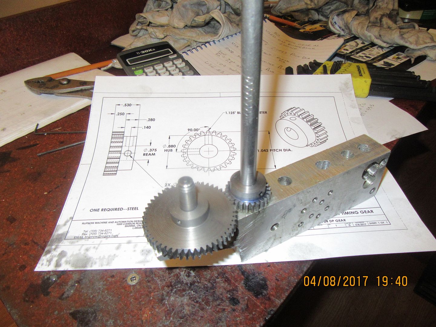
So--Today we made a start. I like cutting gears. I especially like making gears from left over bits and pieces that I have laying about. I always drill a pair of holes the calculated distance apart in a piece of scrap and fit the gears to shafts which set in the reamed holes. It is much better to do it this way and correct any "tightness" in the mesh, rather than trying to do it in a partially assembled engine. These gears seem to be "just right", although that is never a certain thing.
 
Countersunk screws in shear, especially in a dynamic situation, tend to work loose. Fitted bolts in reamed holes is the "proper" way to do it.

If you need more room, the height of the crankshaft could be dropped a little in relation to the main rocker pivot, making the engine désaxé.* Although that would lose some of the pleasing compactness of the design.

Can I also suggest a much smaller shoulder on the cylinder liner instead of the thick flange. This would allow the jacket to bolt directly to the head plate, very much improving the cooling, and allow the liner to be made from a considerably cheaper bit of iron bar.

(* Any reader getting wierd characters, they are supposed to be 'e-acute'.)
 
Has anybody used this type of con-rod connection at the crankshaft?

I used that kind of rod end on my Minnie Traction Engine. To keep the strap tight and accurately located I used a tapered pin between the screws.

Mark T
 
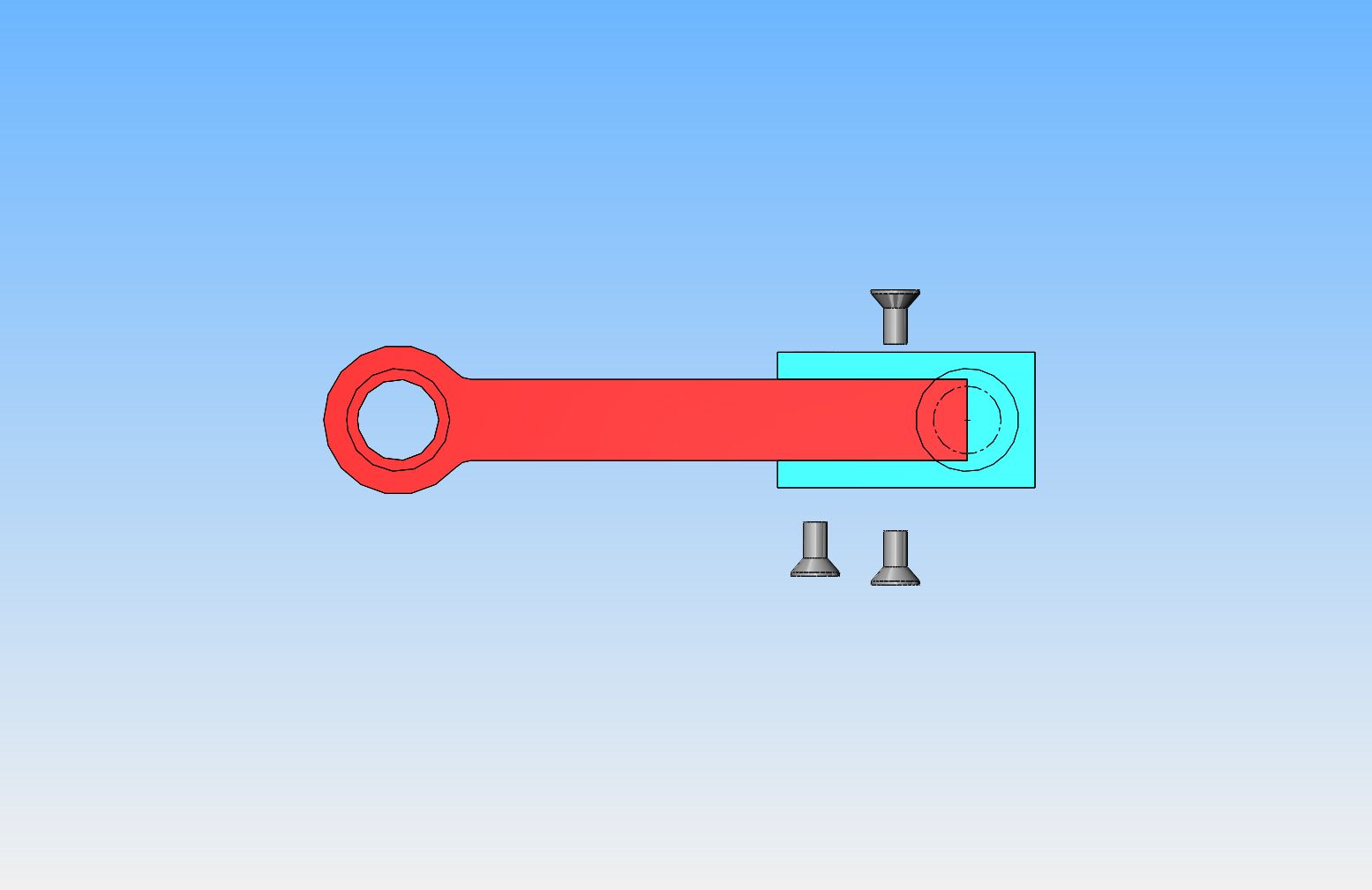
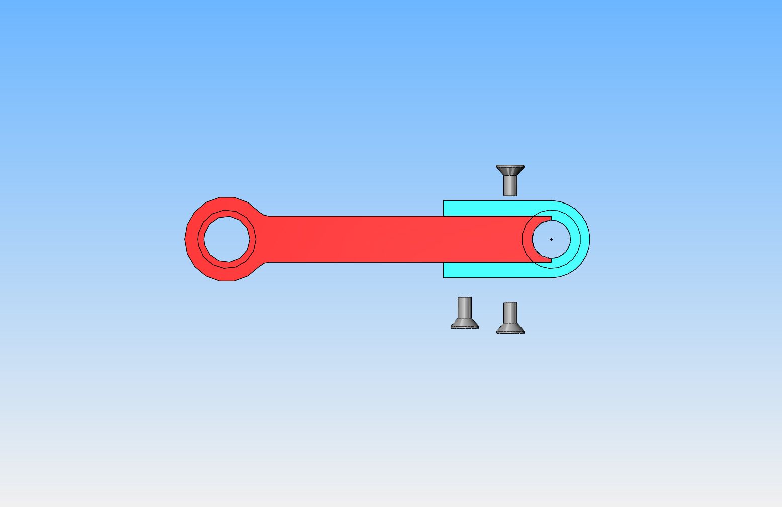
Flat head capscrews as I have shown, also are self centering. You don't need a locating dowel when using that type of screw, although I would probably put one locating dowel between them. I'm still thinking on this one. It seems pretty obvious that the bolted on section would have to be bolted on as a solid piece with no hole to a rod end with no hole. The joint would be right on the split line. The screws are all tightened and a dowel inserted first, then the hole is drilled and reamed after the fact.
 
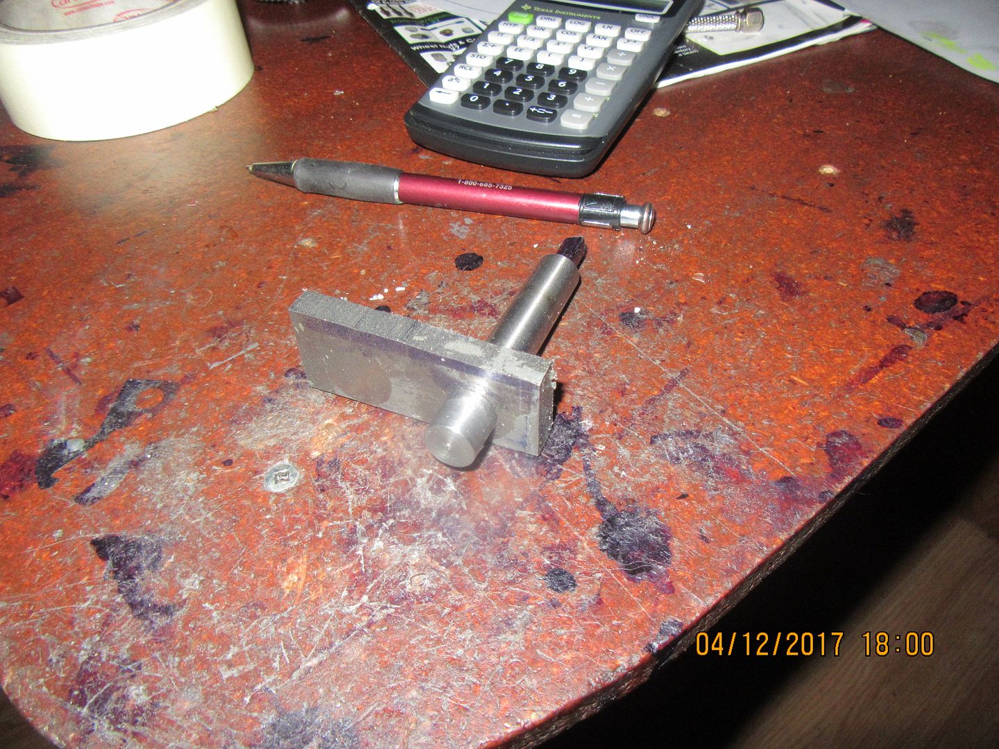
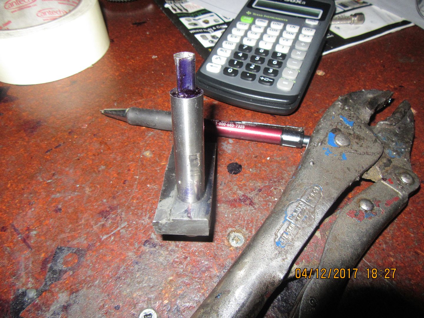
I think that to make the con rod a two piece like I'm thinking of, two separate pieces would have to be machined and bolted (and possibly dowelled) together as shown in the first picture. Then after they are firmly bolted and possibly dowelled together, the hole gets put in as shown in the second picture. The sides would have to be match marked to make sure they went back together the same way they came apart. Then they could be separated and put back together around the rod journal.

 
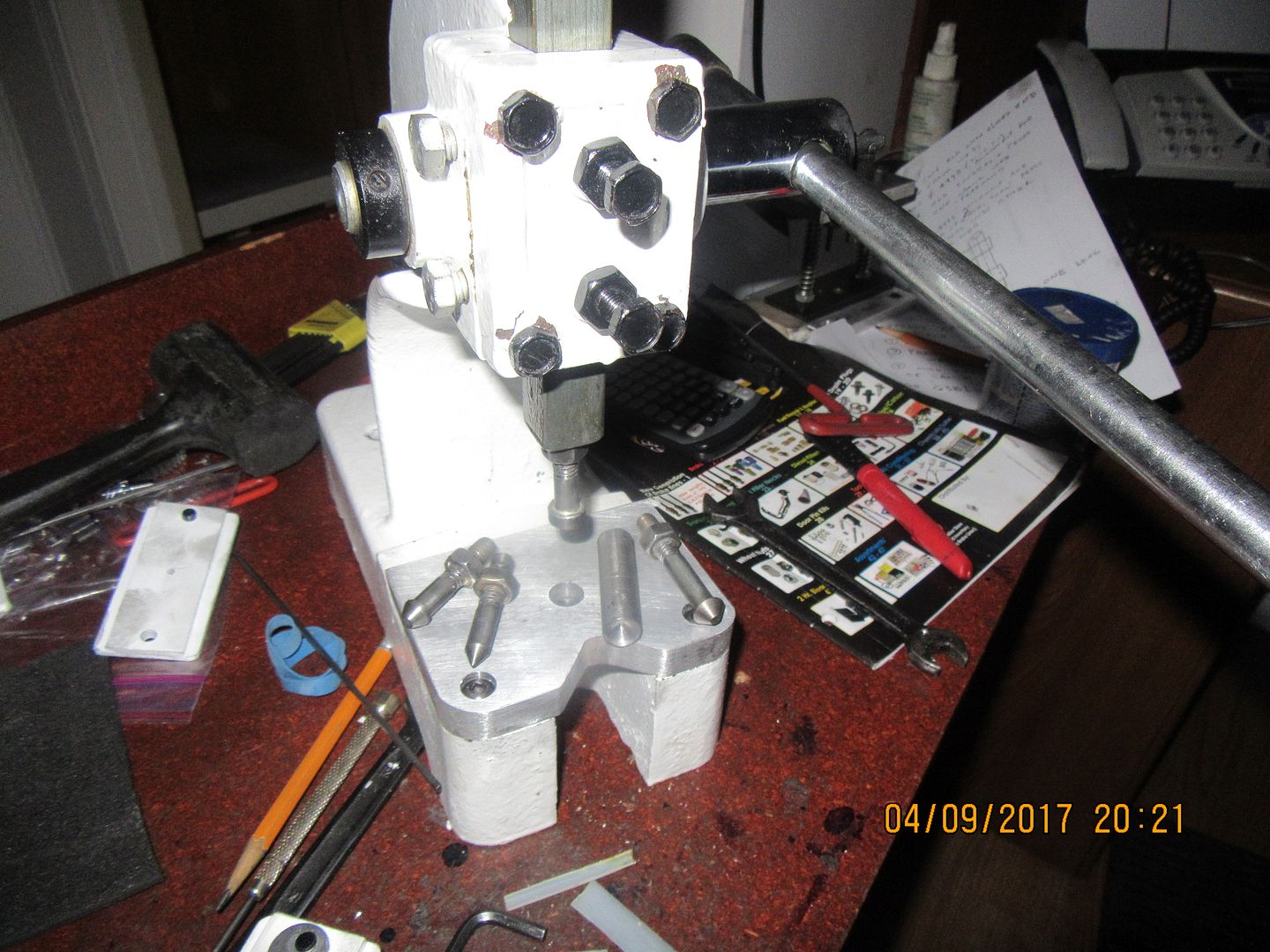
Hey---I'm not just a pretty face!! Sometimes I do real work too. Saturday I made gears. Sunday a customer came by on his way up to the Blue Mountain ski area and left me the smallest arbor press in the world to make some modified tooling for it. It is used for a punching/staking operation which he was previously doing in his vice.
 
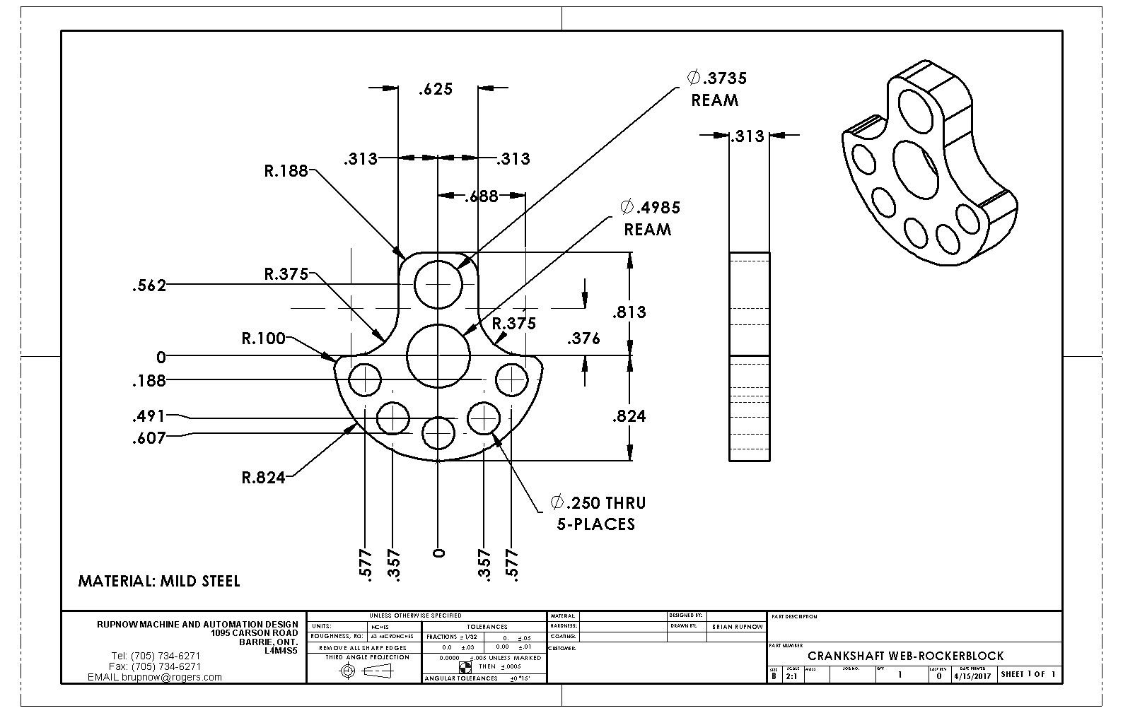
Okay--Back to business. Immediately after I had machined the gears my phone rang about 5 times in a row, each time with a customer I couldn't turn down, and each customer wanted to be looked after "right now". Being a slave to my bank balance, I said yes to all of them, and haven't had time to play "small engine" since. I have discovered one thing, and I'm not sure yet whether it is really a problem or not. When I make built up crankshafts from 3/8" diameter stock, I ream the holes which I am pressing shafts into with a 0.3735" reamer. I use 3/8" drill rod for the shafts, which always seems to come in at .0005" oversize. This gives a VERY hard press fit, with .002" interference, and I have never had one "slip" after the fact. I don't use 3/8" cold rolled steel because it comes in at about .0005 to .0001" undersize, and though it does give a press fit, it is quite a light press fit, and it WILL slip after the fact. Last year I purchased a 0.4985" diameter reamer in case I wanted to make a crankshaft using 1/2" nominal shafting. The problem is, that I just stopped at my metal supplier today and micrometer measured all of their "01" drill rod, and it all comes in exactly at 0.500" diameter. So--I will only achieve a .0015" interference fit. I have to think on this a bit before I proceed. ---Brian
 
Brian,
Have you thought about an adjustable reamer?, Set it to the size that you need and done.

Cheers
Andrew
 
What to do--What to do??--Well, we'll make a little test. I drilled and reamed a 0.4985 hole in a piece of 3/8" mild steel, and I turned a very slight "lead" on the end of a piece of 1/2" drill rod, and I pressed it to see what happens. This type of pressing can not be done on a manual arbor press. It gets done in my vice. This was tight, but not "Oh my God, I've just given myself a hernia" tight. (That's the way it is with a .002" interference.) So, to farther quantify the results (We're getting really scientific here), I put the piece of plate in the vice, clamped my vice grips on the 1/2" round stock, and gave it the old "Reef your guts out" test.--And it slipped---Just like I thought might happen. The fit is tight enough to withstand moderate abuse, but not exceptional abuse such as backfire, pre-ignition, or nuclear Armageddon. I do however, think it would work fine if the components were cross drilled and pinned. Probably with .094" (3/32") dowel pins.

 
Charles, I always use a bit of Loctite 638 when pressing crankshafts. It actually acts as a lubricant during the pressing operation before it begins to set-up.---Brian
 
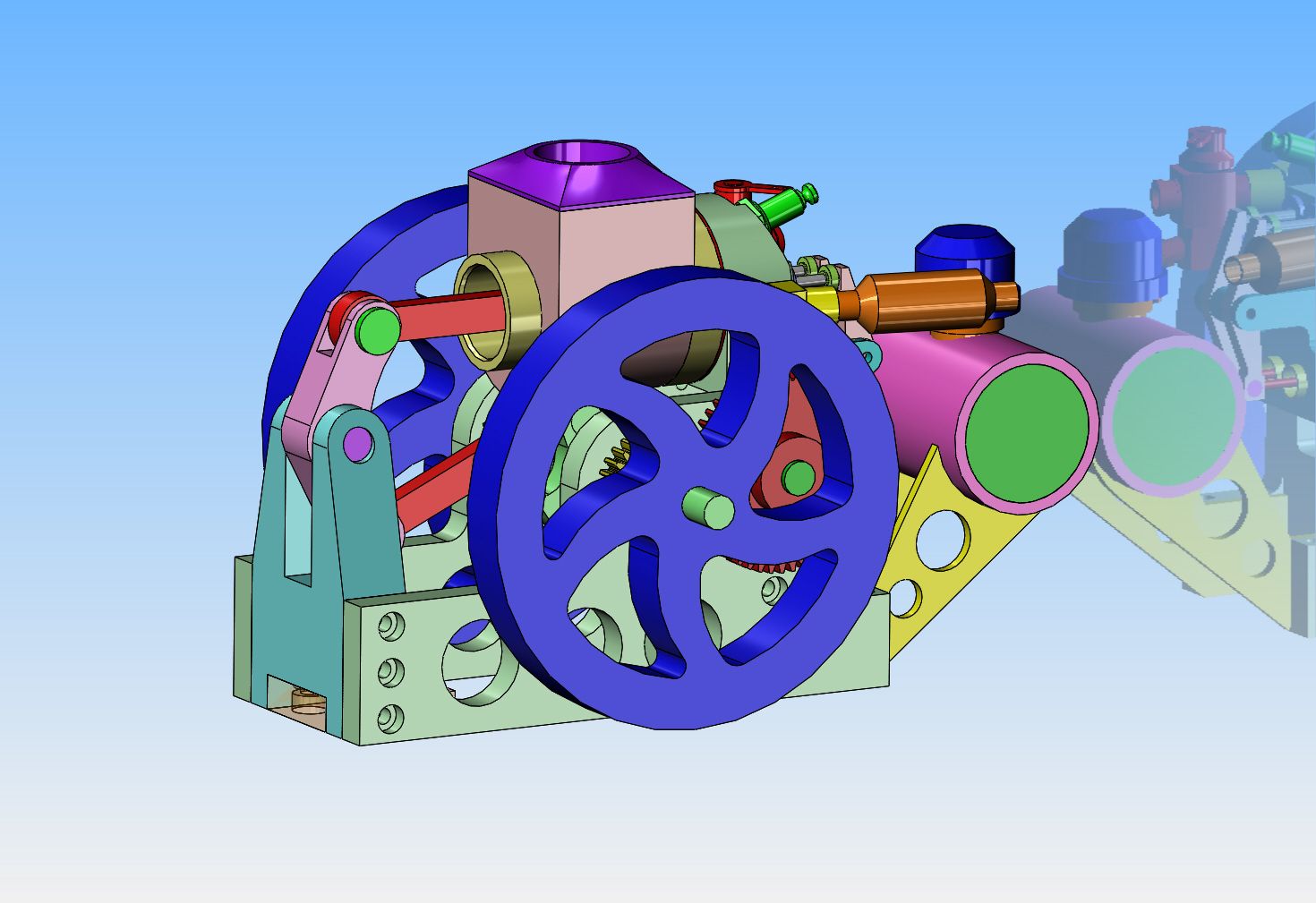
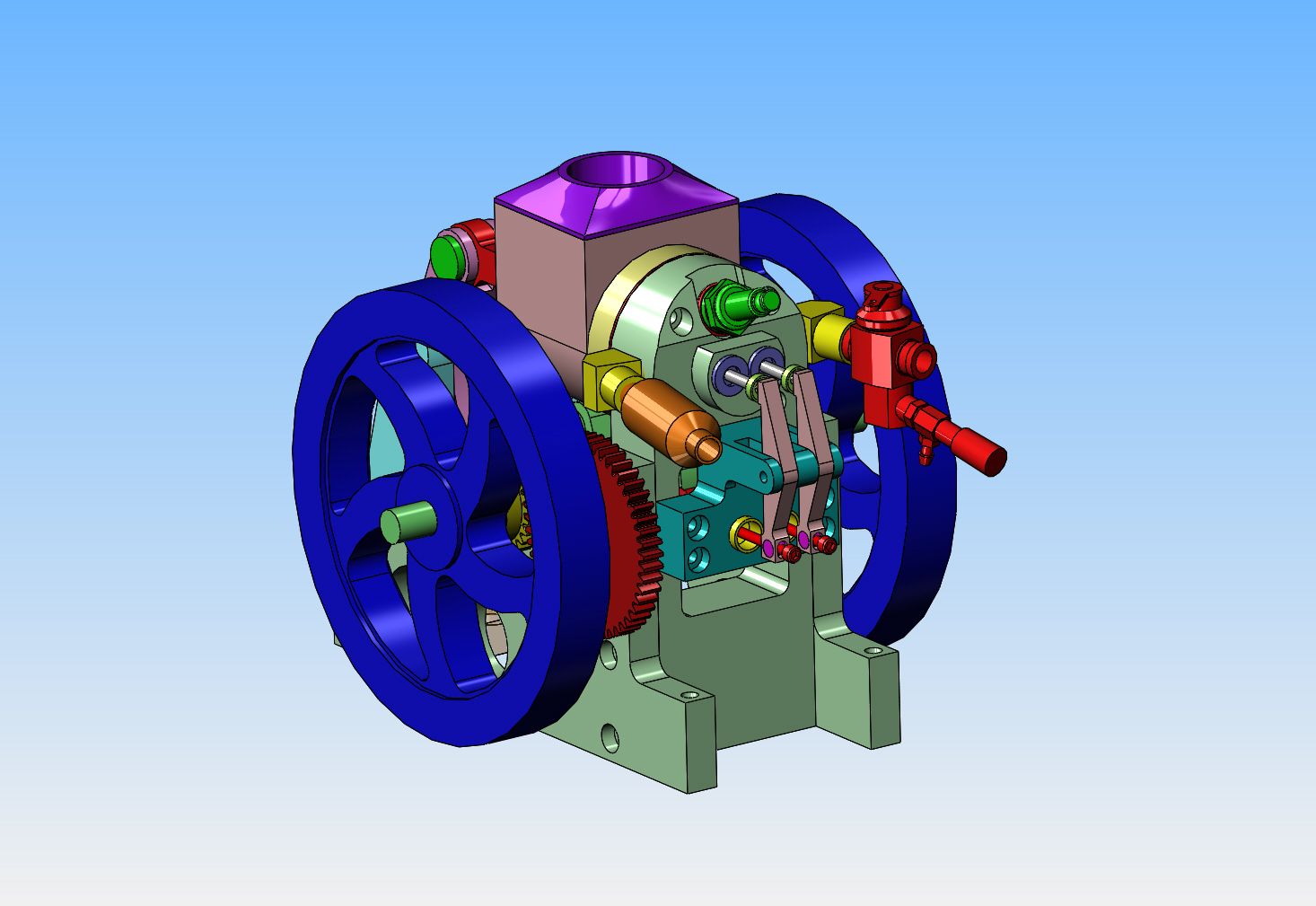
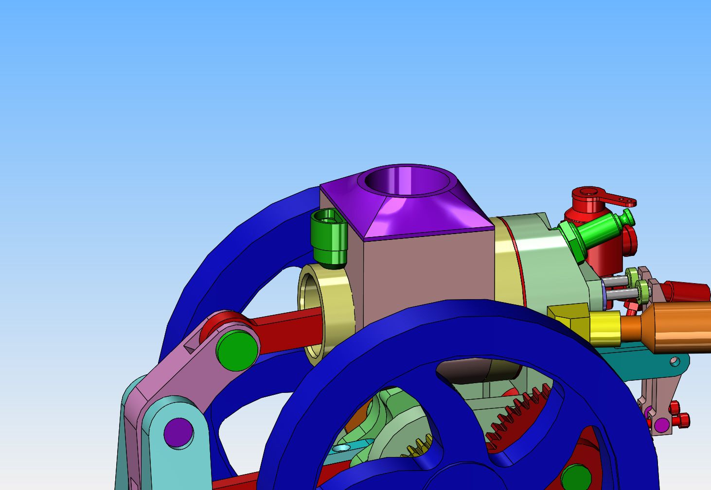
I've been thinkin', Lincoln---if I do get the flywheels waterjet cut, why not do something fancy? so, I got my old Philip Duclos book out and using the information in it, created curved spoke flywheels. I think it adds a lot of "pizazz" to the overall engine.
 
I just ordered Jerry Howells gas valve plans and components to run this engine on propane, and ditched the gas tank. There is just too much beautiful "monkey motion" in those long rocker arms to cover them up with a gas tank, in my opinion. Also, if I do get the water-jet cut flywheels, there will be a relief machined in both sides to accentuate the spoked area.
 
Running the engine on propane is not going to let me mix a little two cycle oil with the gas to keep the viton o-ring lubricated. The simple fix for this is to add a small oil cup with a very small "dribble hole" of about 0.030" diameter to the rear of the cylinder, tucked up tight against the back of the cooling water reservoir. This will let enough oil onto the piston skirt with each revolution of the crankshaft to carry oil thru the rest of the piston stroke and spread it throughout the cylinder while the engine is running. This was very common on the old hit and miss engines.
 
I just got a price to waterjet cut 2 curved spoke flywheels.---$69.50 each. So----I called the guy up and whined at him. The price dropped to $49.50 each. That's 2 1/2 hours setting at my computer designing something for a customer. If I tried to machine them myself I might be 80 years old before I got them finished. I said "Go ahead and make them!!" This should be very interesting.
 
Would one flywheel be enough to run the engine?
If you had one flywheel and a single throw crank one whole side of the engine would be open to see all the movement.

Just a thought.
 

Latest posts

Back
Top