Rockerblock I.C.--Something a little different-

Home Model Engine Machinist Forum

Help Support Home Model Engine Machinist Forum:

This site may earn a commission from merchant affiliate links, including eBay, Amazon, and others.

Brian Rupnow

Design Engineer
Project of the Month Winner
Joined
May 23, 2008
Messages
14,996
Reaction score
8,293
Location
Barrie, Ontario, Canada
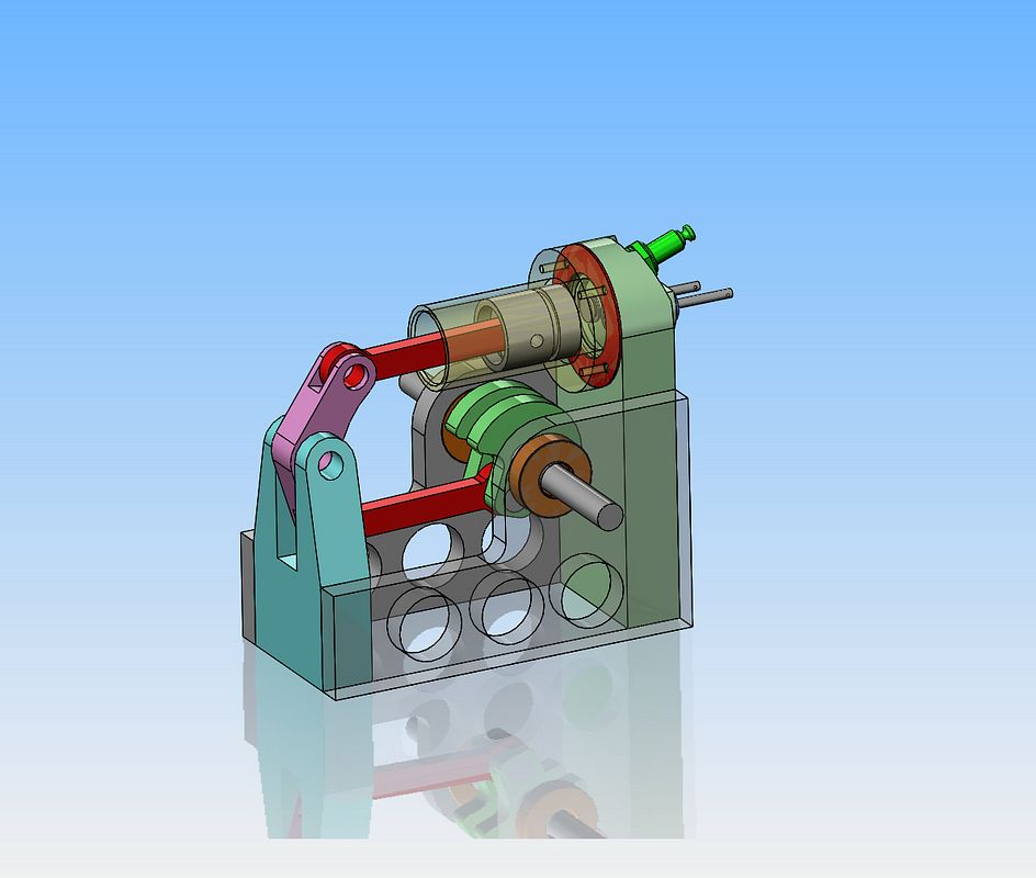
And I do mean different. I want to machine something---but--Something I haven't seen or done before. This is destined to become a water-jacketed engine, 1" bore x 1.125" stroke. I have been casting around for something new to build, and I thought this up last night while fighting off my insomnia. A couple of hours spent on the CAD system this evening just to see if it could be done, and yes, it can. There will probably be many redesigns and changes along the way, but basically this is the overall framework I will stick to.
 
Speaking of the water jacket, my plan for sealing the jacket to the o.d. of the cylinder is shown in this section view of the water jacket. An annular groove cut at each end, just slightly shallower than the cross sectional thickness of a .094 Viton o-ring. Hopefully an o-ring in each groove will seal any water leaks. I will be able to get two or three bolts thru from the flange on the cylinder into one end of the water jacket to keep it from turning on the cylinder.
 
Well Hot-Dog!! I even managed to sneak an ignition cam and my old stand by Chrysler ignition points in behind the offside flywheel.
 
There. That's a solid 8 hours playing. I have to dwell a bit on whether or not I have the crankshaft counterbalances on the correct side of the crankshaft or not, but other than that and a gas tank, the engine design/modelling is finished. Now I have to go shovel out the end of the driveway. We got 5" of April Fools last night. Yuk!! I was hoping we were done with that white stuff!!
 
I always think it sucks to design a nicely proportioned engine, and then stick a gas tank on it. Gas tanks don't leave you with a whole lot of options. They have to be near the carburetor, they have to set below the carburetor throat (but not too far below), they shouldn't block any other equipment which needs frequent adjusting, and they shouldn't be directly in line with the exhaust. That being said, you just do the best you can and hope it doesn't ugly things up too much. This is not an improvement over the normally configured gas engine. It's just a different, artsy fartsy way of doing it.
 
Thanks John--It's amazing, the things I get up to when it's snowing outside and I don't have any "real" work to keep me occupied.---Brian
 
I ended up having to angle both the exhaust and the carburetor out 12 degrees from centerline to clear the gas tank. I could have squeaked by with leaving them "in line" but it would have been severely crowded, and since I have to make the yellow "elbows" anyways, I might as well do this and buy a bit of room.
 
Has anybody used this type of con-rod connection at the crankshaft? I'm pressed for room where my rod attaches to the one piece crankshaft, and this would get me out of trouble. I think the actual hole for the rod journal would be the last step in the fabricating operation so everything would run true. I haven't used this before, but there's a first time for everything.--Brian
 
Dang, this thing is like a big chocolate cake!! All the pieces look so good, I don't know where to start. The beauty is in the simplicity. I shouldn't get so excited about my own work. Every time I do this I swear to myself that I'm going to take it easy, there's no rush, I'll just work on it in my spare time. Then it takes over my life and making another part is all I can think about. Good wife is away at her job in the local library, and won't be home until 3:00, so I think I'll make gears today. Gears are always fun. A bit intimidating, but fun, nonetheless.
 
What good is a build thread without "in process" shots? This is my 50 tooth gear, emerging from another "chucking stub" left over from making a cast iron cylinder. It was barely, barely long enough. I hate doing really short stubs, because if you get to close to those hardened chuck jaws with the gear cutter you can kiss $80 goodbye. The 25 tooth gear which I will do next is on a comfortably longer piece of 1045 steel that was left over from a customer job.
 
Has anybody used this type of con-rod connection at the crankshaft? I'm pressed for room where my rod attaches to the one piece crankshaft, and this would get me out of trouble. I think the actual hole for the rod journal would be the last step in the fabricating operation so everything would run true. I haven't used this before, but there's a first time for everything.--Brian

Two long screws with nuts are better than four short ones.

The easiest way to get acceptable balance is to put weigths on flywheels like steam locomotive wheels.
Either trial and error or doing it up front on Your CAD system.
It will be easier/better if piston mass starts as low as possible
 

Latest posts

Back
Top