Rockerblock I.C.--Something a little different-

Home Model Engine Machinist Forum

Help Support Home Model Engine Machinist Forum:

This site may earn a commission from merchant affiliate links, including eBay, Amazon, and others.
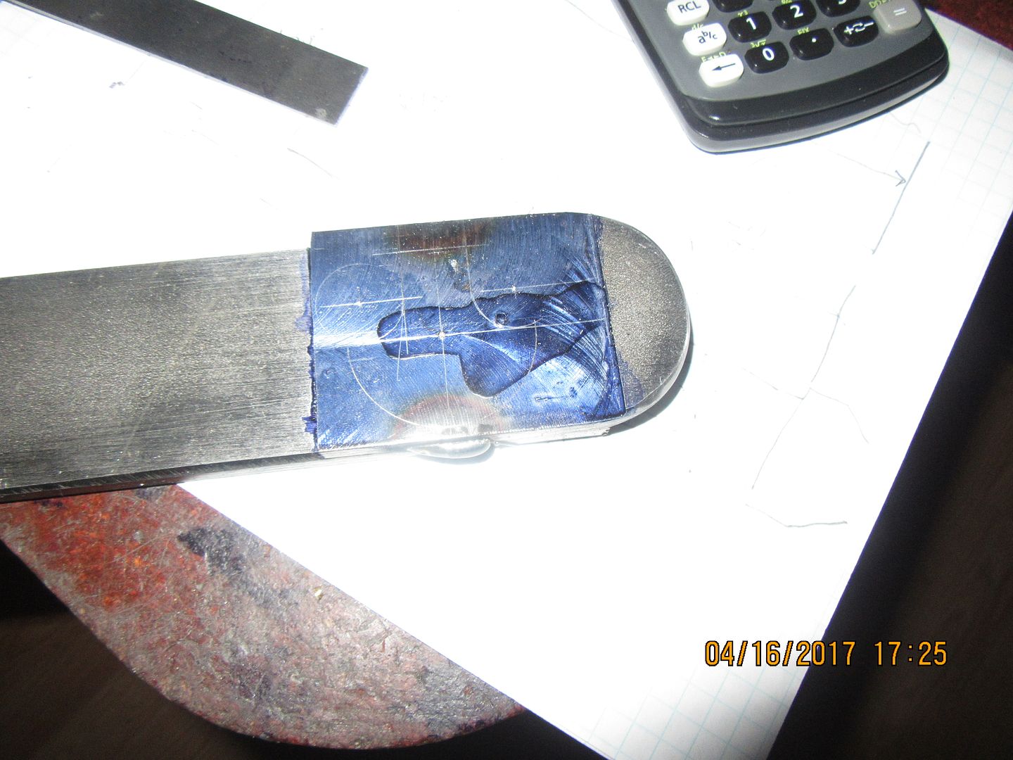
So, here we go again, making it up as I go along. What are you looking at?--Well, I don't have any 5/16" plate, but I do have some 2" x 3/8" steel flatbar. First job was to mill a length of it long enough to make 2 crankshaft webs down to 5/16" thick. Next step was to lay out the profile on one end of the milled down section. Then cut that end off, clamp it tightly to the remaining piece, and run a bead of weld on both sides about half an inch long. This ensures two things. Most importantly, that any holes thru part #1 are going to be dead nuts in line with any holes in part #2. A secondary benefit is that I only have to drill and ream any holes one time. I don't do this in my mill vice, because I don't trust it not to "cock up" a little bit when I tighten the vice. This results in very bad juju on crankshaft webs. I will put a sacrificial piece of plate between this bar and my milling machine bed, and clamp it to the bed for all the drilling and reaming. I will then saw and mill away everything that doesn't look like a crankshaft web, leaving the two welded areas until the very last step before I separate the two pieces. They will be match marked with a center punch so that I don't reverse one or the other when assembling the crankshaft. Crankshafts are one of the things where "Close really does count".
 
The crankshaft webs have been drilled and reamed, then trimmed from the parent stock with the bandsaw. They are still welded together in two places. Next step is back to the mill to square up any "straight-line" surfaces, then mount them on a stub mandrel and turn them to finished diameter in the lathe. I will probably put a bolt and nut through at least one of the "lightening" holes and cinch it up tight so that when the welds get machined away the two pieces of plate won't try and slip and get out of alignment. This wouldn't affect the geometry of the plates in any way, its just that generally bad things happen whenever something tries to "slip" from where you intended it to be when you are machining it.
 
My "Gas demand valve" plans from Jerry Howell came today, along with some very small Tecumseh engine carburetor needle and seats parts and a diaphragm. The detail drawing of the parts I have to make seem to be well done, but it's pretty damned sparse on assembly drawings. In fact, there are no "assembly drawings" as such, just printed instructions that eventually make sense after you have read them and taken all the tiny parts out of the bags and studied on them to see how this thing works. Apparently I now have to buy a propane regulator to use with this thing, and I have no idea what that will cost, but will try to find out tomorrow. I had an email today from the waterjet cutter saying I could pick up my curved spoke flywheels tomorrow, so I'm fair excited about that. I am going nuts right now with design work, to the point where I can't get time to do my own "hobby" stuff.
 
Today we are talking "beautiful things". I went this morning and picked up my waterjet cut flywheels. Man, are they ever nice. These are 3/4" thick mild steel, and the finish on the inside of the cutouts is very, very nice. The man who cut them said he can cut up to 6" mild steel. I will be machining the outside diameter, the 3/8" bore thru the center, and will take a 3/16" deep "face" cut on both sides in the spoke area. I may paint the parts of the flywheel I don't machine. These flywheels are 4 7/8" diameter and have about 1 1/8" diameter inside the cutouts in what will become the hub area. These are the first parts I have had waterjet cut, and although they are pretty, they are not for the faint of wallet. I paid $90 for these two. Fortunately, I got a $100 bonus last week for finishing a "panic" design job ahead of schedule.--that worked out well!!! Laying on my old blue steel handbook you can see my two finished crankshaft webs. If anybody wants the dxf file for these flywheels, email me at [email protected] and I will send it to you. I have to give credit to Philip Duclos for the pretty shape of the spokes/cut-out areas. I didn't copy his numbers, but his "How to" article in "The Shop Wisdom of Philip Duclos" was certainly a big help to get me started in the right direction.---Brian
 
I'm going to get bold here, and do something I haven't done before. Since my crankshaft is built up from individual components pressed, Loctited, and possibly pinned together, I'm going to make up a one piece con-rod and assemble it with the crankshaft. If it works, then great, I'm way ahead of the game. If it doesn't, all I've wasted is a bit of time. Since this is a "demonstration" engine and is not going to see long hard hours of use, I'm not going to run any bearings on the con rod. Aluminum rod running on steel crankshaft lasts a long time if it is kept well lubricated.
 
I'm not blazing thru this build like I have some others, but I did manage to get some machining time in today. The con-rod still has to have the center relieved, but at least I did something. I can't assemble the crankshaft until I have the con-rod finished so I thought this had better be a priority.
 
Brian a lot of my old model aircraft engines con rods were aluminum alloy of some type, plain no bearing and they ran for many hours at high rpm with no sign
of wear or failure.I guess caster oil in the fuel is hell of a good lubricant.
What alloy is best for to use without bushing ? I have a bit of 7075 I was thinking of using but not sure.
cheers
John
 
I got so tired of bodging up temporary fixtures to relieve the center portion of connecting rods that today I actually took an hour and built a dedicated fixture for it. I will post a clearer picture of it when I get the other side of the rod finished. It works like a charm.
 
This is the finished con-rod, along with a shot of the fixture I made for relieving the section of rod between the two end bosses. The round rod in the center is turned to 3/8" x about 0.290" long. The remainder of the round rod is 9/16" diameter and passes thru a 9/16" reamed hole in the flatbar, and is welded a coupe of places on the side which fits into the chuck. The other bolt passes thru the far end of the con-rod and holds it snug against the flatbar, with the help of a flatwasher. The piece of flatbar which sticks out on the other side of center gives the fixture balance and can be tapped anywhere to accept a different length con rod.
 
The first stage of crankshaft assembly is completed. There is a lot going on here!! The large shaft is an alignment shaft only, turned to be "size on size" with the largest holes in the web plates---not a press fit, but a damned close sliding fit. The small shaft is a piece of 3/8" drill rod, at about half a thou oversize. It is a hard press fit (with 638 Loctite) into and thru the first web plate (0.3735" hole), then wiped down with solvent, then oiled and fit thru the bore of the con-rod, then wiped down with solvent a second time and coated with Loctite 638, then pressed thru the second web plate. You don't see it, but there is a "washer" made from cardboard cereal box at 0.018" thickness setting on one side of the con-rod, because the con-rod is squeezed in there very tightly. After an overnight dry, I will make both ends of the crankshaft in one long piece and press it thru all in one blast. After the Loctite on it sets up, I will mill the piece out from between the web plates. Then I will soak the entire thing in water for a couple of hours to dissolve the cardboard washer and give the con-rod some side clearance. One thing to note---When you ream a con-rod to 0.375" diameter, a 0.3755" diameter rod will not fit thru it without pressing. I had to open the bore in the con rod by about .0005" to get a proper fit over the .3755" drill rod. I don't have any oversize reamers, so had to do a lot of persuading to get the bore opened out. This type of "persuading" is accomplished by sanding a taper on a piece of the drill rod in the lathe, coating it with cutting oil, and then CAREFULLY working the rod up and down the taper until it slides over the main diameter.
 
I turned the ends of the main crankshaft down to match the 12 mm sealed ball bearings (that I already had) and left it full diameter in the center area that had to be press fitted to the webs. I coated the critical areas with Loctite 638, and since I have a limited throat opening on my vice, I did it in my two ton arbor press with a cheater bar about 3 foot long on the handle I had prepared a brass "cup" to fit over one end and had my 3 pound hammer ready in case I needed to do some constructive pounding to get things into home position, but they slid right into place on the arbor press, no "pounding" was needed. After pressing things into place, I set it up in the three jaw and checked for runout. Right now it has .008" total indicated runout, which isn't that bad. I just need that figure for comparisons sake when I mill the center portion out tomorrow. If it moves enough to trouble me, I will give it a few good whacks with the dead blow hammer to bring it "true". The jury is still out on whether or not I'm going to pin this crank together or not. Photobucket is being oinky today, but I will put up a picture when it decides to work for me.
 
Tried cutting the throws and the flywheels on the laser at work yesterday.

Wow those throws are tiny - had problems cutting them because the heat had no where to go and the holes just wanted to blow out.
 
My little pile of parts is growing. Today I will finish off the crankshaft, and build the engine sideplates. I made the rocker yesterday afternoon, and for a simple enough part, there are a world of set-ups in it. I used my new con-rod fixture to relieve the material around the bosses on each side of the rocker, and it worked great for that too.
 
And just for the fun of it---here is the crankshaft, luxuriating in it's custom made water filled bath-tub. (which may have been a juice bottle at one time.) I trimmed away all of the unwanted parts this morning. Right now the con-rod appears to be Loctited to everything else, but I'm hoping that with a four hour soak, the .016" cardboard washer on one side of the con-rod will dissolve, and I can break the con-rod free of everything else. I may have to apply a little heat to the center of the con-rod and let it work its way down until the con-rod lets go and decides to turn for me.
 
Barnbikes--Are you planning to build the entire engine, or just taking practice runs?---Brian

Right now I am seeing what I can get done as far as not turning on my lathe. might have to cut the throws with out the holes and do them later.


After a nice break and a drive with good wife, I had to come down and check on the state of my crankshaft, which has been basking in its own private bathtub. The water didn't have as much effect on the cardboard "washer" as I had hoped for. The next trick was to put one end of the crankshaft in my shop vice with aluminum soft jaws and carefully apply some heat to the center of the con-rod, while applying fairly gentle pressure on the con-rod. Once the heat migrated down the con-rod and softened up the Loctite which was preventing it from moving, it began to move freely, and I immediately squirted everything with lubricating oil to keep the heat from affecting the crankshaft itself. The rod now moves freely. I set the crankshaft up in my lathe and put an indicator on it to see if the runout had changed after I cut the center out between the web plates. I discovered that this crankshaft is quite a "flexible flyer". Initially it had about .015" total indicated runout. I grabbed the free end and gave it a tug in the direction it had to move and after doing that a couple of times I had it down to .004" total indicated runout. I had read before about how flexible these single throw crankshafts are, and as I understand it some snowmobile crankshafts with integrated connecting rod are adjusted for runout in the same manner. At any rate, I'm happy, and I think the crankshaft will work fine. I'm not going to pin the pressed connections. Both the rod journal and the crankshaft itself are small enough that I don't want to weaken it by drilling for pins.----Brian
 
Back
Top