poppin crank shaft ?

Home Model Engine Machinist Forum

Help Support Home Model Engine Machinist Forum:

This site may earn a commission from merchant affiliate links, including eBay, Amazon, and others.

BMyers

Well-Known Member
Joined
Jul 9, 2007
Messages
302
Reaction score
4
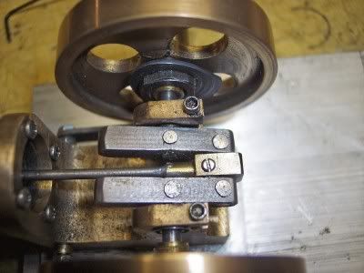
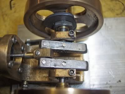
I finally got the standard done for my poppin' engine (see flinging it across the shop). I could use some advice on building the crank. I have never built a crank this small or built up from pieces. My first attempt was less than perfect. I think the parts separated some during the jig drilling (one stacked on top the other). Any tips on how to tackle this part would be appreciated.
 
The Poppin crank was a challenge for me as well.

The plans show fabricating the crank with the main shaft the whole length then cutting
away the center section. I'm a better machinist than that, I could make it from 5 pieces
rather then 4 and eliminate the need to cut that center section away.

WRONG!

I went back to the plans design and made as shown.
The fit was stuff to stuff, meaning it could be put together with a little help from a
light plastic hammer.

Then the joints to the throw beams were soft soldered tight, and the center section
was cut out.

That time it worked!

BTW I have something that resembles the standard for a Poppin in my "Recycle Box" ;)

Rick
 
I brought the crank throws to finished size and then drilled and reamed them individually in the mill. Actually I used a 5/32 end mill that I knew cut a little under size to poke holes through them and then ran a reamer through to finish to size. By taking the backlash out by approaching the hole location from the same direction for both holes, they will be more than accurate enough as far as distance between them. You don't really have to be concerned if the hole pattern if off a little bit from the ends, only that the two holes are the same distance apart on both parts.

In years past I used the match drilling technique by soft soldering two slightly oversize blanks together, then machining them to width and drilling and reaming the holes. Heat and separate the parts and then file off the thin solder layer on each part. The solder removes easily as it is soft and cuts easily.

When assembling, I made a rectangular spacer to fit between the two throws and slid it between the crankshaft and the crankpin tomake sure the two throws were parallel to each other. The crankshaft was made as one piece and everything was assembled using Loctite 680. Then the center section of the crankshaft was removed by sawing, milling and filing.

My finished Poppin is at:
http://www.homemodelenginemachinist.com/index.php?topic=1916.0

Gail in NM,USA
 
Thanks for the advice. I tried to drill the throws both at the same time. I think that was my mistake. I am pretty sure they pulled apart slightly causing the hole to go off square. Because, when i assembled the silly thing one end of the throws was .209 apart and the other was .190. I think next time I will drill them one at a time, clamped to the table.
This project has been a make 2, to get one. I guess I am used to Phil Duclos engines and the nice LARGE parts.
 
Rake,
how did u flux the joints ? I like the idea of soft soldier. I was leaning towards pinning each joint.
 
I just painted the flux on the outside ends of the joints.
I still got a little but of creep into the center journal fit that had to be
polished away.

I'm liking your idea of pinning them even better!

Rick
 
LOL,
I am thinking about using TIG fill rod. any thoughts ?
 
Small parts will warp with high heat.

Sometimes times they return to their original plane but that
would be an exception to the average.

Rick
 
Rick,
I should have been more specific. TIG filler rod as the stock to make joint pins. Not to weld.
 
BMyers said:
Rick,
I should have been more specific. TIG filler rod as the stock to make joint pins. Not to weld.

And I should have seen that! LOL

TIG rods are usually dead on size.
Anything would actually work. Drilling the joint is going to create an internal burr.
Just try drilling through a joint then dismantling it.
Anything you put into that hole as a pin is just reinforcement.

Rick

 
Gentlemen,
thank you for the replies. Crank #2 was a success. I spent last night making a vise stop, so I could mill each throw individually. I used advise from another post of Bogstandard's. I cant wait for the bearings to arrive so I can test spin the crank in the standard.
 
I bragged too soon. crank #2 has terrible run out. it looks great, preforms terrible. Time to rethink this part and try for #3. I refuse to let this part beat me.
 
Don't give up!

My "recycle box" has several short pieces of 5/16" key stock in it with
carefully reamed holes in them. ;)

Rick
 
Hey BM, it's easy when you know how..... That's why I as you do find everything so hard the first ..... erm many times!!

As Rick said, 'don't give up!'

At least you sound like you have found that fighting spirit ;D


Keep us posted on the progress,


Ralph.
 
I think what is so frustrating, is this is my 6th engine. But the tiniest by far, so small errors on a larger engine arent as bad as a small error on a tiny engine.
 
As I said, I liked your idea of pinning the joints.

My Poppin has been run to death and it's time to make a new one.
I was playing with the old crank today and ended up with this:

PoppinCrankshaftPins01.jpg


PoppinCrankshaftPins02.jpg


Those pins are small wire nails I found in the shop.
I drilled the joints for a stuff to stuff fit, tapped the wire nails in and nipped the opposite
ends off leaving about 1/16" sticking out. A few raps with a small ball peen hammer and I
have rivits, or something close to that. :big:

When I do my new build on the Poppin that's what I plan to do.

Rick
 
nice Rake, I used 1/16" fill rod. drilled the holes. pinned it with pins a little long, mushroomed the pins and filed smooth. The pinning worked good. I need to get a 5/32 ream, drilling isnt working for me. Maybe after 4 or 5 I'll get a system worked out
 

Latest posts

Back
Top