PMC IMP Build log and WIP

Home Model Engine Machinist Forum

Help Support Home Model Engine Machinist Forum:

This site may earn a commission from merchant affiliate links, including eBay, Amazon, and others.
Please recognize that this post contains a lot of personal opinion.

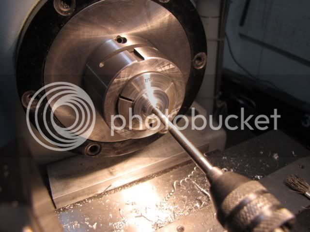
With all the machining done on the cylinder, the bore must be finished. For the hobby machinist there are two methods in common use, honing and lapping. So which did I use? I am not sure. The definitions of the two processes have been merging for some time, and differ some from one industry to another.

Traditionally, honing was defined as a process using vitrified stones to finish a bore. Lapping was defined as using a loose abrasive in a slurry.

In more modern times, honing definitions have expanded to include abrasive, mostly diamond, that has been bonded to a metal core. Electroplating nickel, like a diamond file, is a common way to bond. Sometimes the tool is is adjustable, or is less critical applications is it fixed. A common name for this process is single pass honing. Oil is normally used to wash out removed metal particles.

Lapping has also expanded, and is sometimes referred to as wet or dry lapping. Wet lapping is where a slurry of abrasive is used between the lapping tool and the part. Dry lapping is where the abrasive is pressed into the tool to impregnate it. The tool is then cleaned of all loose abrasive. Despite the name, dry lapping is not done dry. Oil or other liquid is used to wash out the metal particles as they are removed from the part.

So, at the overlapping point, the only difference between lapping and honing is is method used to secure the abrasive to the tool. I am going to call the process that I use lapping as it meets the definition of dry lapping.

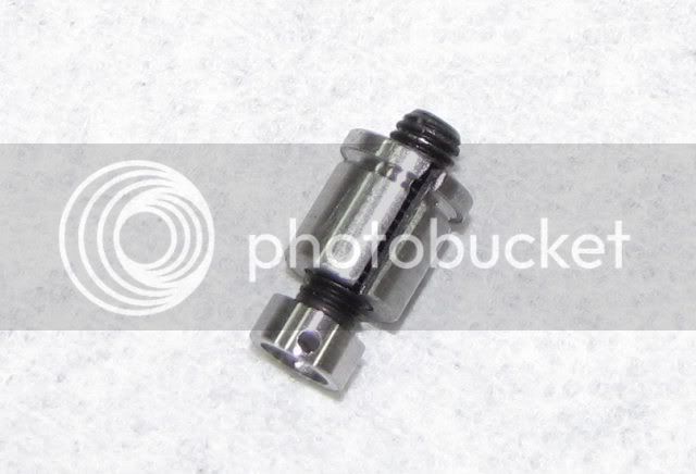
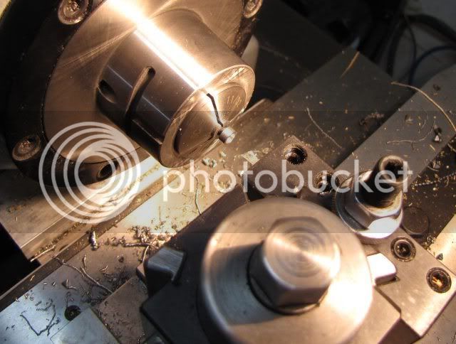
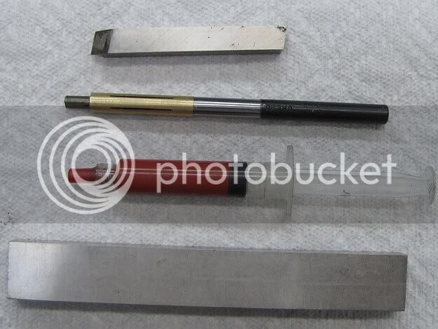
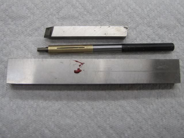
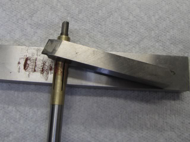
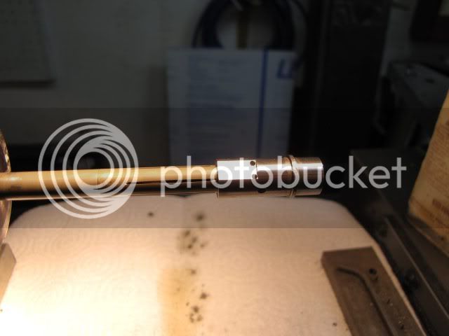
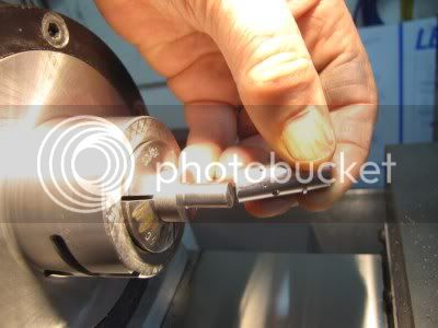
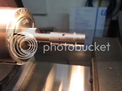
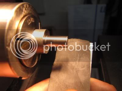
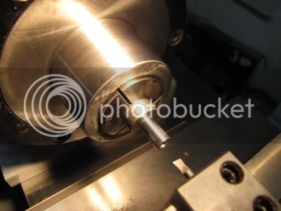
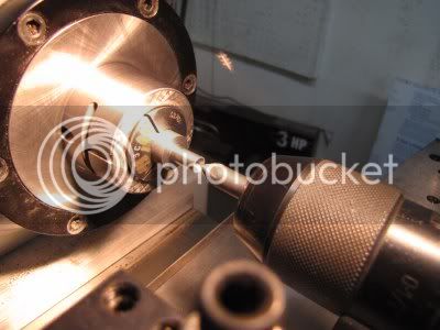
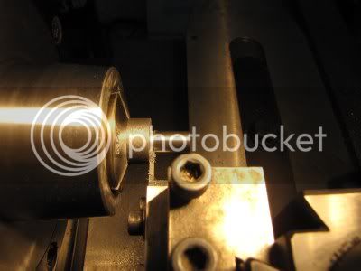
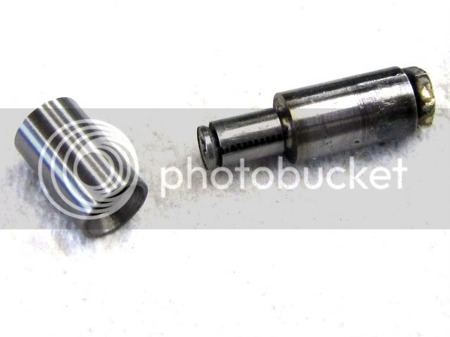
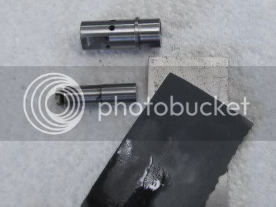
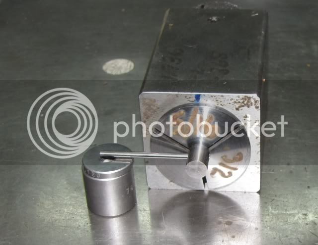
I used a pair of commercial expanding lapping tools with a brass barrel. As the operations are identical only one will be shown in the photos.

For abrasive, I use diamond lapping pastes. when dry lapping, I do not believe that diamond is worse about embedding in the work than the silicon carbide and other abrasives used in valve grinding compounds, or that it makes any difference. While some other abrasives will break down easier than diamond, if any abrasive of any kind is left in the bore, the piston/cylinder set will be worn out long before the abrasive breaks down.

I use two different grades of diamond. Because the terminology used to grade abrasives can get confusing I am including more information than you probably want to know. The syringe in the photo is a 5 gram syringe. It is hard to see if any has been used. While I have not kept count, I have lapped over 20 cylinders from 1/4 to 3/4 inch bore with this syringe. A 5 gram syringe costs about US$20 at Enco. I do not expect to ever use up the contents of this syringe. The compounds I have are medium concentration. This is just how much diamond is mixed in. Light concentration would work just as well, but a little bit more of it would be used.

For roughing the cylinder, I use 600 mesh diamond. 600 mesh is roughly the equivalent of 380 grit if you compare it to wet-or-dry abrasive paper and the particle size is a nominal 30 micron, or about 0.0012 inch. This roughly is the same as Clover compound 1A.

To finish the cylinder, I use 1800 mesh diamond. 1800 mesh is roughly the same as 800 or 1000 grit wet-or-dry and the particle size is a nominal 10 micron or about 0.0004 inch. This roughly is the same as Clover compound 5A or 6A.

The Clover compounds referenced are silicon carbide, not diamond.

End of opinion and background information. Next post will be the how-to part.

Lap1.jpg


To charge the lap with diamond, a small amount of compound is placed on a hardened surface. I used an old odd size parallel that was in a box of junk that I bought at a machine shop auction. One of those deals where I wanted one thing in the box and the price was right.

The blob of paste is about 3/32 inch diameter. It does not take much.

Lap2.jpg


The paste is spread out to form a patch about 1/2 inch long and the width of the parallel. If the paste is not spread out, then a lot gets pressed into the grooves of the lap. Then I used a 3/8 square ground tool bit to roll the lap back and forth in the paste using firm pressure. The position of the lap is changed every few strokes to make sure the entire surface of the lap is covered. Always roll the lap. If you slide it the lap will mostly just pick up the diamond in the slits in the lap. Probably 1/2 of the diamond ends up there anyway.

Lap3.jpg


Clean the lap with mineral spirits or other solvent and wipe dry with a paper towel. Clean the parallel and tool bit and then THROW the paper towel away. You don't want it around where you might wipe down a machine tool surface with it. I seldom use rags in the shop as they can be a safety problem around power tools, and I NEVER use rags when working with abrasives.

If you look at the lap at this point, it will not look any different than when you started. Mark the lap by engraving the shank or some other method so you will know what grit the lap is charged with.

Now repeat the process with the other compound, again making sure to mark the lap with the grit used.

You can NOT clean a lap that has been charged with coarse grit and then use a fine grit. Once charged with a grit, a lap must always be used with that grit.

This photo shows a portion of a lap charged with 600 mesh diamond as seen under a 200 power microscope. The dark spots are diamond. This lap has seen quite a bit of use. The scratches in the brass are probably caused by particles of the metal being lapped. Remember the dark spots are only about 0.001 diameter so the scratches are not very deep.

Next up will be the lapping of the cylinder.

Lap600mesh200X.jpg


Gail in NM,USA
 
Before lapping we have to define the bore we want to lap. For a small compression ignition (CI)engine, such as the IMP, it needs to be a little bit different than many other engines. On larger bore, low compression ratio, and engines with rings the bore is most often just required to be round and parallel. Because of the high compression ratio on CI engines the cylinder pressure needs to be about 180 PSI or so before the engine will fire. This means that the piston/cylinder fit must be very good. As the diameter of the bore decreases this becomes more of a problem as the volume is proportional to the cube of the diameter and the sealing area is pproportional to the square of the diameter. To achive the tightness of the seal required, it is more or less standard practice to taper the cylinder bore a very small amount so the piston becomes a tight fit at top dead center. Different people do this in different ways. This is what works for me.

When working with any form of abrasive in the lathe, I move the carriage toward the tailstock end of the bed and then cover the bed with a plastic sheet. Then I put a paper towel over the plastic sheet. Never use a rag for two reasons. One: A rag can get caught on the rotating part or chuck jaws and be a safety hazard. Two: When I am done, I throw the paper towel and plastic sheet away so there is no posibility that I will wipe or other wise contaminate a precision surface with anything that may contain any abrasive.

First off I start with the lap that is charged with 600 mesh diamond. Apply lots of very light weight mineral oil to botht eh lap and the inside of the cylinder. The lap diameter is adjusted to just have a light drag on the cylinder. The lap is chucked in the lathe and the lathe is set to run about 300 RPM. Start the lap from the bottom end of the cylinder. The cylinder is slid back and forth over the lap and will free up very quickly. Adjust the lap larger and repeat. I move the cylinder about two times per second. The lap should not be so tight that you can not hold the cylinder with your fingers grasping firmly. Each time, or at least every other time, that I adjust the lap, I rinse the part in a container of mineral spirits to remove any slurry of metal particles. I use a tube brush to clean it out. Wipe the lap with a paper towel moistened in mineral spirits. The put a fresh coating of oil on both the cylinder and the lap. I repeat this until all the machining marks in the cylinder are removed and the bore is uniform from end to end. I can feel if there are any tight or loose spots on the bore with the lap.

Clean the cylinder very well with mineral spirits and a tube brush. At this point there is a distinct crosshatch pattern in the cylinder. The grooves created by the lap may be up to about half of the diameter of the diamond grit, or about 0.0005 deep.

Clean the lap and tag it with the grit or put it in a marked bag so it is ready for the next use.

Next I move on to the lap that is charged with the 1800 mesh diamond. The same procedure is used as was used for the previous lap. As I dropped two grades in the size of the diamond, I do not try to remove all the grooves created by the previous lap. I like to do the equivelant of what is known in automotive circles as "plateau honing". There are peaks and valleys left by the previous lapping, and I want to remove about half of the peaks and leave the remaining valleys to retain lubrication. This means only increasing the diameter by about 0.0005 inch or so. None of it is very critical, but it makes for a shorter break in on the engine and a longer life. These little engines are not known for a long life time anyway.

Finally, I put a taper in the bore from the bottom end of the cylinder up to about the top of the exhaust ports. The taper only needs to be about 0.0003 or 0.0004 inch on the diameter. I just expand the lap and then run the cylinder on the lap part way. I just approximate the distance from where I feel the lap start to cut.

Clean everything !! Throw away the paper towels and plastic covering the lathe bed. As a last cleaning operation on the cylinder, I scrub it with hot water and detergent, making sure I get everything out of the various ports. Then I oil the cylinder with light oil to prevent rust.

It probably took you longer to read the last few posts than it takes to lap a cylinder. It certainly takes less time than it took me to write it. Depending on how good a job id do on boring a cylinder and the resultant finish, it takes me from 15 to 20 minutes to lap a cylinder from set up to tear down.
Gail in NM,USA

Cyl9.jpg


The cylinder on the IMP is spaced up from the crankcase with a spacer. The only unusual thing about this is that the original IMP was supplied with three spacers rings. The normal one was installed on the assembled engine. The two additional ones were slightly longer and shorter that the normal one, and could be changed to vary the timing of the engine. Not a big advantage as the timing on everything changed. Intake, exhaust, and transfer all shifted. For completeness I made all three, but doubt that I will ever try the two additional spacers. They are a simple turning and parting off job. As they need to be gas tight, each one received a rub on both faces on 600 grit abrasive paper.

CylinderSpacer.jpg
 
With the cylinder finished, the piston and contra piston are next. Both are carefully fitted to the cylinder, but in a different manner. Both are made of cast iron. I started with the piston.

The goal on fitting the piston is for it to almost jam in the cylinder when it reaches what would be top dead center (TDC) in operation. I try to get it so by the time it reaches the point where the skirt of the piston reaches the top of the transfer port opening on the cylinder it takes about one pound force or a bit more. At this point the piston is beyond the taper portion of the cylinder and should be able to be forced through the cylinder if one really wanted to try. All this is necessary to make sure that a near perfect seal happens near TDC. If it won't hold the 200 psi necessary for ignition to occur here then the engine will not fire.

I started with a length of 5/8 diameter continuous cast iron rod. Most of the distributors don't have cast iron below 1 inch. Speedy Metals is one of the few places I have found that has it down to 5/8 inch. When I get a new length of cast iron I clean up the whole length to the largest size that I have collet that will fit. The cast iron rod is always oversize enough to at least clean up to the nominal size. In this case, the rod cleaned up to 0.671 (43/64). I do this so the rod will clamp firmly with no danger of rocking on a high spot while machining. With an inch or so of the rod extending from the collet I turn it to a few thousands over the measured size of the bottom of the cylinder. Then i carefully start dusting off the diameter until the piston will just start to enter the taper of the cylinder.

Piston1.jpg
Piston2.jpg

Photo 1

I then polish the piston until it will enter about half way in the cylinder using 600 grit abrasive paper with a little bit of light and backed with a ground piece of steel that is wider than the piston. I use a parallel for the milling machine vice.

The piston is center drilled, drilled and bored to form a flat bottom recess in the piston.

Piston3.jpg
Piston4.jpg

Photo 3

With a 60 degree counter sink I chamfered skirt of the piston to reduce the wall to about 1/2 of it's thickness and then cut the piston off leaving about 0.005 to 0.010 extra length to clean up.

Piston5.jpg
Piston6.jpg

Photo 5

Since the piston fit in a standard collet, I cleaned it up to length by chucking in a collet and facing the end until it was the correct length. I could have been done on the mandrel in the next step also if I did not have the correct size collet.

An expanding mandrel was made from a short length of 5/16 steel, the same nominal size that the piston is. I turned the end of the mandrel to fit the piston internal bore and reduced the diameter of the shank to a little less than the diameter of piston for an additional 1/2 inch. The mandrel was drilled for about 3/4 of it's length with a clearance drill for a 4-40 bolt and then drill through with a tapping drill size. The end was counter sunk to match a flat head 4-40 bolt. The mandrel was reversed in the collet and the other end tapped 4-40. In the milling machine, I slit the mandrel with a 1/32 slitting saw. I turned the head of a long flat head 4-40 bolt down so it would fit inside the piston and then screwed it into the mandrel. At he far end I secured a nut on the thread with a dot of silver solder with the nut spaced out from the end of the mandrel an 1/8 inch or so.

Piston7.jpg
Piston8.jpg

Photo 7

The piston was slid on the mandrel and secured by expanding the mandrel using the nut on the far end. I gripped the mandrel at an angle in the corner of my milling vice to tighten the nut with both piston and the nut outside the vice jaws.

Back to the lathe I polished the piston with 800 grit and oil in the same manner as shown in photo 3 using a steel backing plate. The piston was cleaned with a paper towel and mineral spirits before test fitting in the bottom of the cylinder. When I got near the fit I wanted, I switched to 1200 grit to finish to the desired 1 pound force when the piston skirt was at the transfer port.

The piston was moved to the milling machine and the wrist pin hole was center drilled, drilled and reamed. The hole was deburred with a bit of 1200 grit abrasive paper. Cast iron does not leave much of a burr if the tools are sharp.

Piston9.jpg
Piston10.jpg

Photo 9

I gripped the piston in a collet in a square collet block. By inserting a rod in the wrist pin hole and using a spacer block while tightening the collet, the wrist pin hole was aligned to the collet block.


Piston11.jpg


With collet block in the milling vice, I milled the transfer notch into the side of crown of the piston. The photo shows the notch being cut for V3 of the engine, where the notch is cut on side of the piston that has the wrist pin hole. For versions V1 and V2, the block was rotated 90 degrees so the notch was parallel to the wrist pin. The edges of the notch were deburred with 1200 grit abrasive paper.

Piston12.jpg


Gail in NM,USA
Edited to add slitting mandrel and correct spelling.
 
kvom,
A transfer notch is cut into the side of the piston to deflect the incoming fuel/air charge toward the top of the cylinder to help force the combustion products out of the cylinder while keeping the new charge in the cylinder. As the notch uncovers the transfer port in the cylinder the charge from the crankcase comes up, bends 90 degrees to pass through the port, and then bends back 90 degrees upward. The "Z" bend was not the most efficient way of doing things but it worked and was quite popular on small compression ignition engines designed in the 1940's into the 1960's.

On glow and spark ignition engines of the same era, it was more common to machine a baffle, or in some cases bolt one on, into the top of the piston. A recess for this baffle was then machined into the cylinder head to keep it from striking the cylinder head. This was not practical on a compression ignition engine as the top of the cylinder was closed with a movable contra piston to adjust the compression and it would be difficult to keep it aligned with the piston. Some CI engines used a domed piston with a matching recess in the contra piston. This did not work very well as the incoming charge was spread to the sides about as much as it was deflected upwards.

A good solution was developed and has become known as "Oliver" porting and is in wide use today. With it the transfer ports are at an angle to the cylinder so the fuel charge is brought into the cylinder at an upward angle so no baffle is necessary. This is what Bob (Maryak) did on his Maryak 10 engine and is illustrated in his build photos at:

http://www.homemodelenginemachinist.com/index.php?topic=3712.msg40335#msg40335

and the cylinder plans at:

http://www.homemodelenginemachinist.com/index.php?action=dlattach;topic=3629.0;attach=3193

Gail in NM,USA
 
Gail,

Coming along great guns. :bow:

As I read it you are using a similar technique for fitting the main piston to the bore as used to make the contra piston, (Dave Owen method). Much easier than a couple of hours lapping. Thanks for the tip :bow:

Best Regards
Bob
 
Thanks Bob,

It's not the same as the Dave Owen contra piston method in that the piston not tapered but the lower portion of the cylinder is tapered. There is no compression of the piston skirt. I get away with using abrasive paper in that the piston is turned to less than 0.0005 of the finished diameter. Most of the diameter reduction is just removing tooling marks from the turning. I have used both this method and lapping in the past and can't tell any difference. I know that the abrasive paper will knock it out of round a little bit (much less than I can measure), but lapping a short length will often cause a barrel shape. So if figure that if I am going to have an error either way I will take the lazy man's way out.

Next up will be the contra piston, on which I do use a variation on Dave Owen's method. It is by far the easiest method to get a good contra piston seal with an o-ring seal, which I have also used, running second. Some people have worried about the deterioration the O-ring when using them, but I still have a OK Cub 0.074 cid of about 1955 vintage that I bought new and used a lot and the O-ring in it is still fine. Still, I like the Dave Owen method better for it's simplicity and it is easier to fit.

Gail in NM,USA
 
rklopp said:
Gail,
My Little Dragon fired up on the second or third finger flick!! Subsequent starts required the electric motor, until the thrust from the motor chewed up the bearing behind he prop driver. Like you, I've moved on, and the Little Dragon is now a "shelf queen."
RKlopp

The solution is to use a thin shim stock steel washer between the aluminum parts. This was done in plain bearing production engines.

Charlie
 
radfordc said:
The solution is to use a thin shim stock steel washer between the aluminum parts. This was done in plain bearing production engines.

Charlie

A steel washer works well. However, so does brass or even phenolic; as long as it is smooth on both sides, doesn't cause any binding and is a different material than the thrust washer and crankcase. My preference is to use brass and polish up both sides although I have been meaning to try one made of hardened or case hardened and polished steel to compare long term. And, before running the engine put a few drops of fuel or just plain oil on the crankcase/washer/thrust washer.

Cool threads and builds. Very inspirational. One of my long term goals is to build a small diesel (CI) to put on a Tomboy or Buzzard Bombshell (reduced size). I am making sketches and keeping notes - soon I keep telling myself, all I have to do is clear out some of the projects first.

cheers, Graham in Ottawa Canada.
 
With the piston and cylinder complete, only the contra piston remains of the trilogy of parts that must fit together properly. If any of these are not fitted properly a small compression ignition engine will not run.

For the readers who are not familiar with compression ignition model engines, the contra piston fits into the cylinder from the top end and is adjustable to adjust the compression ratio of the engine. Unlike a diesel engine where the timing is adjusted by when the fuel is injected into the cylinder, a model comprssion ignition engine's timing is dependent on three things.

First is the fuel components. About a third of most CI fuel is ether, and it evaporates easily. So A fresh batch of fuel will react differently than one that has the can opened a number of times.

Second is the fuel-air mixture, which on a small engine like the IMP is adjusted by a conventional needle valve operating in a spraybar in the intake air stream.

Third is the compression ratio. This is what the contra piston changes.

The contra piston must be a tight fit in the cylinder. Any leakage around the contra piston and a small engine will not run. On the IMP, I tried to get a fit such that it took about 5 pounds force to press the contra piston into it's normal operating position. With the high compression ratio, about 15 pounds force will be applied to the contra piston as the piston passes top dead center if there is no leakage. This pressure goes much higher when the engine fires.

With that bit of theory out of the way it is time to make the contra piston.

At the time the IMP was produced, the standard way to make a contra piston was to just make a short solid piston that was a tight fit in the cylinder. It was not uncommon for home builders to make several before they got the right fit. A few years ago David Owen developed a method that made a perfect fit almost automatic. He made a hollow piston that had thin tapered walls that would compress as the piston was pressed into place. For more on his method see:
http://modelenginenews.org/faq/index.html#qa7
http://modelenginenews.org/weaver/Weaver_pg6.html#DCO_CONTRA

To taper the contra piston, I first set the compound to 1/4 degree. On my lathe this is easy to do as the side of the compound slide is accurately ground parallel to the dovetail. I have a dial indicator that I can clamp in the headstock that I use for this. A magnetic mount on the lathe ways would also work. Since the tangent of 0.25 degrees is 0.0044, the compound is set so the indicator moves 0.0044 when the carriage is moved 1 inch.

Contra1.jpg


Next the contra piston was turned about 0.003 over the measured size of the cylinder bore at the top of the cylinder using the carriage feed. It was turned from the same cast iron that the piston was made from. I turned to a length of 0.325 which allows for the 0.25 inch finished length plus enough for my cut off tool plus an extra 0.01 for cleanup later.

With the carriage locked in position I started making taper cuts on it until it would just start to enter the cylinder about 0.03 inch. Then I started reducing the taper section with 800 grit abrasive paper using a steel backing the same as I used for the piston. I reduced it down until the contra piston would enter about 1/2 way into the cylinder and then cut it off from the stock.

Contra2.jpg


Changing collets in the lathe, the piston was reversed and faced to 0.25 length. Then it was counter bored to a depth of 0.187 and a diameter to leave a wall thickness of 0.015.

Contra3.jpg


Gripping on about 1/3 of the length, the skirt was polished with 1200 grit abrasive paper, again using a steel backing. I would polish a little bit, and then remove from the lathe a test fit it in the cylinder until it was reduced to a point where I could press it into the cylinder with about 5 pounds force.

If you try this procedure, be sure that the piston in NOT in the cylinder before you start test fitting the contra piston. With the contra piston in one end of the cylinder and the piston in the other it is most difficult to remove either one of them. ;D ;D

Gail in NM,USA
 
Gail,

Soon we will hear the lovely purr from another of your fantastic engines. :bow: :bow:

Video is mandatory, :p ::) well please make one. ;) ;)

Best Regards
Bob
 
another great craftsman here!

chapeau :bow:


great documentation too
 
Thanks Bob and Ariz.

Another little part. The wrist pin. No photos of it, but it will show up in later photos.

The wrist pin is just a length of steel rod to connect the connecting rod to the piston. On the IMP it is 0.093 diameter and about 5/16 long. It needs to be a tough steel as it has a lot of stress on it. I have broken two on small compression ignition engines over the years. One that I had made and not drawn the temper far enough so it was too brittle, and one commercial one on an Allbon Dart (0.5 cc I think). The Dart was broken many years ago and I replaced it with a section of music wire and it is still going strong. So I have used music wire where I could ever since.

The music wire I use is the straightened type found in model airplane hobby shops in 3 foot lengths. It is hard drawn and has very hard skin on it with a tough core. It is fairly round in most cases, but I take a micrometer with me when I go shopping and select looking both for roundness and oversize.

Since I am building 3 engines, I made 4 pins - one to lose. I started with a long length of music wire chucked in the lathe. I had previously measured it and it was just a little oversize, and after deburring the end this was verified by trying it in a connecting rod. Running the lathe at about 2000 RPM I polished the wire with some 1200 grit abrasive paper and oil while backing it with a smooth piece of steel. It only took a minute to polish about 1.5 inches untill it was a smooth fit in the connecting rod.

After removal from the lathe, I used a Dremel tool with a thin cut off blade to cut off 4 lengths about 0.025 long. To clean up the ends, I chucked each piece in a battery powered electric drill and ran it against a fine, freshly dressed, grinding wheel in the bench grinder. After cleaning up each end, I continued to grind the pin until it was about 0.002 shorter than the cylinder bore. Then I polished the ends using a non woven abrasive wheel in the grinder, again using the drill. By rocking the drill, I put a slight radius on each end to roughly match the bore of the cylinder. This completes the wrist pin.

On the IMP, the wrist pin floats, that is there is no means of retaining the pin to keep it from touching the cylinder and no room for end pads. For that reason that the ends must be polished to keep from damaging the cylinder.

Referring back to the cylinder, each port consists of two holes with a bridge between them. When the engine is assembled, the cylinder is aligned so the wrist pin rides on this bridge so it can not get caught in a port.

Gail in NM,USA
 
With the wrist pin done, all the parts necessary to relieve the inside of the crankcase are complete.

The crankcase assembly is inserted into the crankcase. As it is a close fit, it was not necessary to use any screws to hold it in place. The piston is connected to the connecting rod with the wrist pin. The connecting rod is slipped onto the crankpin on the crankshaft. The cylinder is slid on to the piston and into the crankcase while rotating the crankshaft so the crankpin is at bottom dead center. By rotating the crankshaft, I could see where the connecting rod would hit the crankcase. The whole mess was disassembled so the crankcase could be relieved and the process repeated until the connecting rod cleared the crankcase with a little extra clearance.

For photo and details on reliving the crankcase see:
http://www.homemodelenginemachinist.com/index.php?topic=4422.msg47296#msg47296

Gail in NM,USA
 
Sorry for the break in this WIP. I had a visiting model engineer here for a week and we were working on other projects. Then I had a bit of surgery and that slowed me up for a few days.

The next part will make the IMP start to look like a real engine. The finned cylinder head is really a fairly easy part. There are no close tolerances and it is large enough to be easy to handle.

Starting with 7/8 diameter aluminum bar stock in the lathe, the end is faced off, then drilled to to a depth to allow boring to size. The bar is bored to a depth of 0.318 and a diameter about 0.001 over the size of the top of the cylinder. Small compression ignition engines do not generate a lot of heat, so a slip fit between the cylinder and the head is adequate to dissipate the heat generated when running.

Head1.jpg


Next the four grooves forming the five fins are cut using a 1 mm parting tool. A slow feed and a sharp tool are necessary as well a a little bit of cutting fluid. I use Tapmatic Edge and apply it with an acid brush where the bristles are pushed into the groove as it is being cut.

Head2.jpg


Using a metal rule and a bit of 400 grit abrasive paper the inside fo the grooves are lightly polished and the edges of the fins are lightly beveled just enough to break the sharp edges as I like the square edge look on the fins. When using the rule in the groove, it is better to run the lathe in reverse so the friction is pulling on the rule rather than pushing it. That way if it binds a little from being out of line it does not bend and bind more.

Head3.jpg


I parted the head off a little over length and reversed it in the collet. After cleaning it up to length I turned a section to 1/2 inch diameter I rounded the edge of the top using a corner rounding end mill. It was then polished before removing from the lathe.

Head4.jpg


The remaining lathe operation is to center drill, drill, and tap the top for the 10-32 compression adjustment screw.

Head5.jpg


Moving the head to the milling machine, head was centered using a dial test indicator. For the V1 head, two holes were center drilled and drilled as clearance for 4-40 bolts. For the the V2 and V3 head four holes were drilled for 2-56 clearance. The holes were located by coordinates using the X and Y handwheels. I used a very sharp drill with cutting fluid and slow feed to keep burrs between the fins to a minimum.

Head6.jpg


Gail in NM,USA
 
Gail,

Beautiful work. :bow:

This will, I'm sure be the most impish of Imps. ;D

Best Regards
Bob
 
Thanks for the kind comments Bob.

At the very top of the engine is the compression adjustment screw. It is used to adjust the compression ration by positioning the contra piston in the cylinder. It only needs to push as the compression and firing of the engine will keep the contra piston in contact with the screw.

While a commercial screw stuck in the head and adjusted with a tool will work, a modified or purpose made screw will work much better.

I started off with a 10-32 socket head cap screw. I first made a split collet out of alumninum that was a little shorter than the desired finished length of the screw. The small diameter needs to be smaller than the head on the screw, and a single slit can be a hacksaw or band saw cut. The center hole is drilled for the major diameter of the screw. It is shown in the first photo along with a nearly finished screw.

Compression6.jpg


I first turned down the OD of the head to get rid of the serations on the head that would make cross drilling difficult and then removed the hex inside with a small boring tool. This was so the drill would not be deflected by the flat sides of the hex. As the head was taller than I wanted I cut some off the top.

Compression1.jpg


Moving to the mill, I held the split collet in a small vee block and center drilled the screw head following by cross drilling with a 1/16 drill bit.

Compression2.jpg


Compression4.jpg


Back to the lathe, the screw was reversed in the split collet and the end faced off and center drilled. I also shortened it as it was longer than I wanted. The edges of the thread were beveled to keep them from touching the contra piston.

If the end touching the contra piston does not have the center relieved, the screw will "walk" when the engine is running. It is frustrating to have the engine adjusting it's self.

Compression5.jpg


Finally, and with no photo, a piece of 1/16 music wire 3/4 inch long was kinked slightly in the middle and pressed into the cross hole. The ends were buffed so they would not be sharp before pressing it in place. I mixed a small amount of epoxy glue and added a bit of black coloring to it and ran it in the head around the music wire. I made a little mound on top and turned it off after it had set.

Gail in NM,USA
 
A couple of quickie things and the main assembly can be done.

First a couple of gaskets. The gaskets were made from 0.006 thick vegtable fiber gasket paper. I cheated and cut them on a laser engraver that I have available, but they are easy enough to cut by hand. The square one is for the V1 model and the round one for V2 and V3. V2 and V3 take two each, one for the front bearing assembly and one for the rear cover.

Gaskets.jpg


Gail in NM,USA
 

Latest posts

Back
Top