PMC IMP Build log and WIP

Home Model Engine Machinist Forum

Help Support Home Model Engine Machinist Forum:

This site may earn a commission from merchant affiliate links, including eBay, Amazon, and others.
Although it is not part of the engine, a knob to help adjust things is worth while. Just something to turn the crankshaft while fitting the connecting rod to it, and later to adjust the position of the contra piston. A propeller can be used, but it always seems to get in the way. Of course a few washers stacked up will also work, but a knob is so quick and easy that it hardly seems worth while to improvise.

Knob.jpg
 
All the parts necessary to assemble the engine are now made except for the exhaust pipe, fuel assembly, and for a couple of things that are nice, but not necessary to make the engine run.

The assembly starts with the piston, connecting rod, wrist pin and cylinder. I wipe a thin film of oil on all the parts as I assemble them except I put a good drop on the connecting rod at the wrist pin. I just use 20 or 30 weight shop oil.

Assy1.jpg


With the piston, wrist pin and connecting rod assembled, the piston is inserted into the cylinder. The transfer notch on the piston has to face transfer passage on the cylinder.

Assy2.jpg


The cylinder spacer is added to the bottom end of the cylinder and the cylinder is inserted into the crankcase and aligned so the intake and exhaust ports on the cylinder line up with the intake and exhaust openings on the crankcase.

The contra piston is inserted part way into the cylinder and the head bolted down to hold it all in place.

A gasket is placed on the crankshaft/front bearing assembly and it is installed in the front of the crankcase while guiding the connecting rod onto to the crank pin. A good drop of oil here is also a good thing. On V1, this assembly is glued in place with epoxy, so the crankcase and front bearing are cleaned before assembly and epoxy used to secure it all, and no gasket is used. On V2 and V3, assembly is secured with six 0-80 screws.

Assy3.jpg


Gail in NM,USA
 
With the head bolted on, the compression adjustment screw is run into the head until it touches the contra piston. The piston was adjusted to top dead center by rotating the crankshaft and feeling where top dead center was. Then the compression adjustment screw was tightened to move the contra piston down until it touched the piston. Again by feel and by rocking the crankshaft a little bit it was easy to tell when they touched and the screw was backed off until they did not touch.

The space between the top of the cylinder head and the bottom of the head on the compression adjustment screw was measured and a spacer made to fit on the screw was made. The length was made equal to the measured distance plus 0.010 inches. With the spacer in place, the screw can not press the contra piston closer than 0.010 to the piston.

The nominal operating compression ratio of 18:1 had been calculated to be with the contra piston to piston distance of about 0.025 inch. Since the compression screw has a 32 pitch thread, the operating point for the engine should be about 1/2 turn up from bottoming on the spacer.

Gail in NM,USA

compression7.jpg
 
Very nice work GailInNM :bow:
The last couple of close-up pictures nearly makes one forget the cylinder is about your thumb's thickness!

Regards, Arnold
 
Very Nice GailinNM :bow: Can't wait for the run video!!
Tony
 
Thanks Arnold. You got me curious with the thumb comment. I keep forgetting to put a size reference in the photos.
I ran a caliper over my thumb, and it measured 0.95 inch at the joint. The IMP cylinder is 0.87 inch diameter. Overall height is the length of my thumb, close enough. At 5'6" (almost) I am not a very big man so most thumbs will be larger. ;D

Tony,
This WIP is a compilation of three similar engines. It is being done after the fact except for a bit of tinkering and a few parts being made where I was not happy with the first ones.

The first one was run in March and there is a linked video of it at:
http://www.homemodelenginemachinist.com/index.php?topic=4338.0
The other two been run also, but no video shot. I was not planning to post video of V1 and V3 as they are essentially the same engine with different external features and run the same.

Gail in NM,USA
 
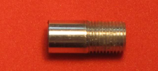
In post 62 I detailed how to make the compression limiting sleeve, but I did not give all the reasons for using one. After all, most of the commercial compression ignition engines do not have any means to limit the contra piston position. The only really early popular engines that I remember that did so were the OK Cub engines.

If you read the early operating instructions of the commercial engines, most caution against using an electrical starter. That is fine advice, but if you watched the IMP video you know that I used a starting motor. About a dozen years ago I found that I could either hand prop engines or the next day I could raise my arm enough to do machining in the shop. NOT both.

When hand starting a small engine you can feel if a hydraulic lock is developing or if the compression is set too high. You lose this feel using an starting motor.

On V3 of the IMP, I fitted the piston a little bit loose, but thought I would try running it anyway. Not really loose, just that the pinch point on the piston position was about a tenth of an inch higher than it should be. So the piston was really less than 0.0001 inch too small. Thats too much for small CI engines like the IMP.

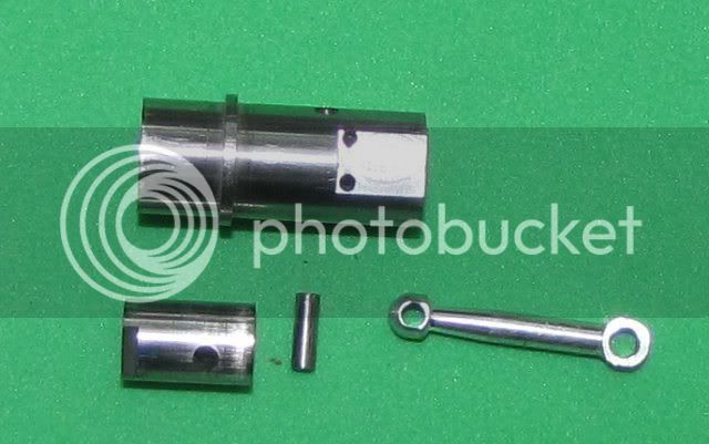
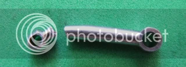
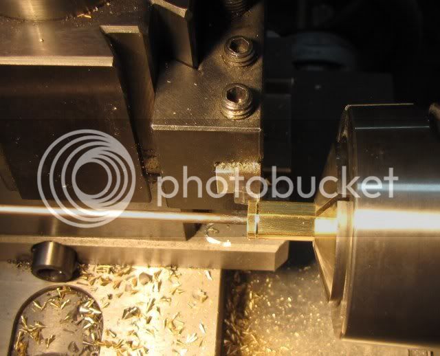
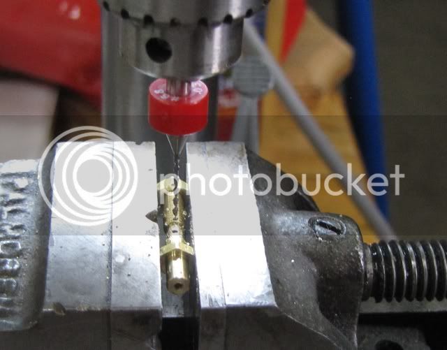
Since I was just trying it, I did not make up the compression limiting sleeve. I lost track of the position of the contra piston and ran the compression screw down a little too far while tinkering with start up. Since the con rod is the weakest link in these engines, the photo shows the result. :( :-[

New piston, properly fitted, and a new con ron and all was well. ;D

Gail in NM,USA


Opps1.jpg
 
OUCH - At least you could re-make it!
Regards, Arnold
 
Gail,

Bad luck :mad: but I agree about the options of a start of the engine v continued use of your arms and back.

Best Regards
Bob
 
Arnold:
It was not as big an OUCH as one might expect. If you noticed when I was making the connecting rods I was making one on each end of some bar stock so I had something to chuck on. So, I had made 4 and only needed 3 and that left me a finished up spare. When I blanked the pistons, I cut an extra couple of blanks that I left slightly oversize and did not put the transfer notch in as the transfer notch is different on V1/2 and V3. So just had to finish to size (the right size) and cut the notch. All told it only took about an hour from broken rod to running.

Bob:
It really was not "Bad Luck". Just me being my optimistic self with a "maybe it will run OK" when in my heart I knew that I would have to rework it at some time to make it run right. Most of us get a little lazy sometimes and try to cut corners. I am one of the worst offenders, but don't mind remaking parts when necessary.

The main reason for including this in this WIP was to explain why I did something the way I did. I normally don't mention the stupid mistakes I make. Those are just part of building toy engines. When I mess up a part beyond recovery I make a new part and get on with it. But, I get irritated when instructions say "don't EVER do this" and then don't say why. Also, beginners to engine building need to know that no matter how many engines you build, you are still going to make mistakes. Making parts over is a life long part of building engines.

Gail in NM,USA
 
Getting close now. Only the fuel system for all three versions and exhaust stack for V2 and V3.

The fuel system is the same for all three versions. The photo shows all the parts to be made except the 1/4 jam nut used to lock in into position when screwed into the crankcase.

No detail on the spring will follow, It is just 10 turns of 0.018 stainless steel spring wire wound on a 1/8 inch diameter mandrel. More than 10 turns have to be wound as it will spring open when the winding tension is removed. When it springs open, the ID opens up to a little over 0.140 diameter so it will slide on the smaller diameter of the needle barrel shown on the center right of the photo. I close wound the spring and then spread it so 10 turns covered 1/2 inch, more or less. It's purpose is to keep the needle valve from changing position from vibration when the engine is running.

Gail in NM,USA

FuelParts1.jpg
 
I did the jam nuts first. Mostly because I wanted a jam nut to help hold the spraybar later for cross drilling, but also because they are easy and I wanted to get them out of the way. I needed 5 jam nuts 5/16 AF (Across Flats) with 1/4-40 threads and 3 nuts 3/16 AF with 5-40 threads. Thickness is not critical so I made them 0.080 thick because I have a 0.020 parting tool ground up. 0.080 + 0.020 = 0.100 and that is a nice increment for slicing them off.

Same method is used for both nuts. Photos show the 1/4-40 nuts being made.

Stock is center drilled, drilled and tapped as deep as the tap would go. Then sliced off. Step over and slice off another one. A thin rod was held in the tail stock drill chuck so the nuts would not fall into the chip tray. Then the faces of each nut was cleaned up with a fine file to remove the cutoff burr. It is a big burr because of the thread.

Gail in NM,USA

Nut1.jpg


Nut2.jpg

 
GailInNM said:
Most of us get a little lazy sometimes and try to cut corners. I am one of the worst offenders, but don't mind remaking parts when necessary.

The main reason for including this in this WIP was to explain why I did something the way I did. I normally don't mention the stupid mistakes I make. Those are just part of building toy engines. When I mess up a part beyond recovery I make a new part and get on with it. But, I get irritated when instructions say "don't EVER do this" and then don't say why. Also, beginners to engine building need to know that no matter how many engines you build, you are still going to make mistakes. Making parts over is a life long part of building engines.

Gail,

More power to you for your words of wisdom and how you obtained the wisdom. :bow: :bow: :bow:

Best Regards
bob
 
Next up is the spray bar. It is at least more exciting than the nuts.

The spray bar has a lot of operations on it, and the most intimidating one for most people, the cross hole, is by necessity the last operation.

I started with 3/16 AF hex brass stock. Round stock could have been used, but the hex makes it easy to align and tighten the spray bar when it is installed in the venturi. I turned it to 1/8 inch diameter for 5/8 inch and then threaded that 5-40 to a point that is about the middle what will be the reduced section.

It was carefully center drilled and then drilled 1/16 diameter to a depth about a 1/16 inch beyond where the cross hole will be. Then the hole was continued with a 0.040 drill to the finished length of the spray bar. For both of these drilling operations it is essential that the drilling only go about 1-1/2 times the diameter of the drill and then with draw the drill to clear the chips. These holes must be straight and if the drill is pushed too hard it will wander.

Spraybar1.jpg
Spraybar2.jpg


Spraybar3.jpg
Spraybar4.jpg


Using a 1/16 wide parting tool, the section that will be in the venturi hole is reduced to 0.093 and the radius left by the turning tool is squared up next to the 3/16 hex section. Then the stock is extended from the chuck and the spray bar is cut off to length.

The part is reversed in the lathe, griping on the 1/8 diameter section. and the other end in turned down to 0.093 and a small groove about 0.010 deep is cut to aid in holding the fuel line on. A liberal bevel was filed on the end to make it easier to install the fuel line.

Spraybar5.jpg
Spraybar6.jpg


Gail in NM,USA
 
The last operation on the spray bar is to drill the cross hole.

I threaded a nut on the spray bar and then clamped it in a small (1-1/2 inch) drill press vice. As I was clamping I turned the vice upside down on a flat surface. The points on the nut and the hex part of the spray bar then brought the spray bar level with the top of the vice. This positions the hole with the point on the hex and makes alignment easy on final assembly.

Drilling was done with a 0.032 carbide circuit board drill in a small high speed drill press running at 10,000 rpm. A stop had been set so the hole would only go through one side of the spray bar. Positioning is not critical. It just needs to be some where near the center of the reduced section of the spray bar and close to the center line. The circuit board drill has a sharp self centering point and is short and stiff so it does not wander when starting the hole as long as I am close to being on the top center of the bar. I wore a 10 power magnifying hood while positioning the drill and then fed slowly. After drilling I ran a 1/16 inch drill bit in the threaded end of the bar with my fingers to remove any burr that may have developed on the inside.

Spraybar7.jpg
 
Now for a venturi to mount the spray bar in.
Started with 3/8 diameter 6061 alumnium. Turned down a 1/2 inch of it to 1/4 inch diameter and drilled a 0.140 hole 1-1/8 deep. The finished length will be 1.062. Then threaded 1/4 inch of the end 1/4-40 to match the crankcase.

Venturi1.jpg
Venturi2.jpg


Switched ends of the part and faced off to length. Set the compound on the lathe to 10 degrees and cut the external flare. I used a home made taper cutter with 20 degree included angle to cut the inside taper. Most of the time I use a small boring bar to cut this sort of thing as the compound is already set at the correct angle, but since I had the taper cutter on hand it was quicker and easier than mounting a boring bar.

Venturi3.jpg
Venturi4.jpg


While I still had the 1/4 inch collet in the lathe a made up the exhaust stacks. They are just a 1/4 inch diameter rod 1/2 inch long and drilled through 3/16 inch diameter. Then threaded for 1/4 inch 1/4-40, the same as the venturi.

Exhaust1.jpg


I then moved the collet from the lathe to square collet block and put the venturi in the collet block. Clamped the collet block in the mill vice and milled two flats on opposite sides of the venturi, turning the collet block 180 degrees after milling the first side. This was followed by center drilling and drilling 1/8 diameter through for the spray bar.
Gail in NM,USA

Venturi5.jpg
Venturi6.jpg

Venturi7.jpg


Gail, you do make it all look easy ;) ............ first class thread and very informative, thank you, I'm looking forward to the rest :bow:

CC
 
Very nice going Gail :bow:
Kind regards, Arnold
 

Latest posts

Back
Top