PMC IMP Build log and WIP

Home Model Engine Machinist Forum

Help Support Home Model Engine Machinist Forum:

This site may earn a commission from merchant affiliate links, including eBay, Amazon, and others.

GailInNM

Administrator
Staff member
Administrator
Global Moderator
Joined
Feb 17, 2008
Messages
2,326
Reaction score
440
About 10 days ago I made the first run of a sort of replica version of a PMC IMP. A couple of photos of it on the test stand and a short video of it's second run were documented at:
http://www.homemodelenginemachinist.com/index.php?topic=4338.0
I promised a construction series on it and this is the start of that. There will be details left out, mostly because I forgot to put them in. If there is something specific that you would like more information on, just ask. I may not have the answer, but you can ask.

This whole thing started in early November 2008. As I often do, I was peeking around on the ModelEngineNews.org web site and happened across the PMC IMP. Here are a couple of links to information on the IMP from there. If you are interested, do a search on the site and there is more information.

http://modelenginenews.org/cardfile/pmcimp.html
http://modelenginenews.org/ed.2005.09.html#3

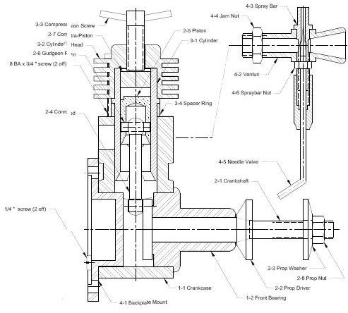
In addition, Ron had prepared CAD drawing by reverse engineering an IMP, and those drawings appear in the "members only" area of the site and are included in the DVD that he has prepared for members of the site. The drawings have a few minor omissions in them, but nothing that would prevent construction. After looking at them for a few days, I sketched up 3 versions of the IMP. On all the versions, Imperial screws were substituted tor the BA screws on the original.

Version 1 is fairly much as the IMP was originally constructed. It is a fair representation of the IMP, but there were quite a few variations of the IMP. As only a few were built, and they were hand built, it is probably fair to say that almost every one was a little bit different.

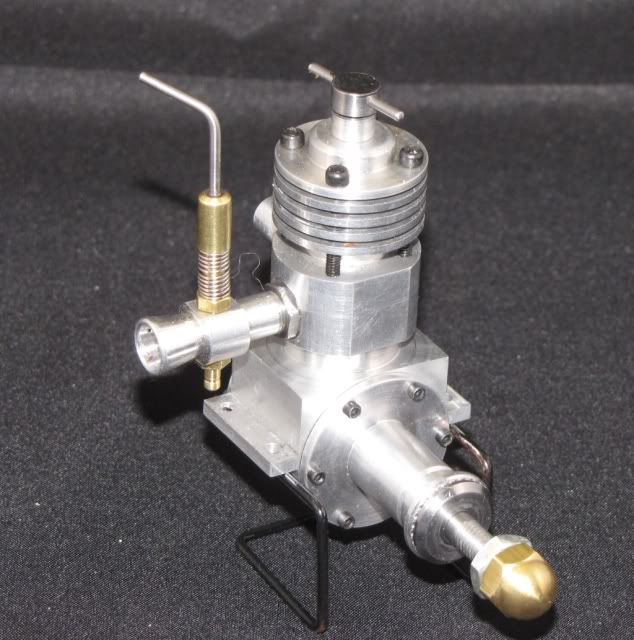
Version 2 of the IMP is mostly the same as Version 1, except the front and back plates for the crankcase are screwed on, beam mounts added, and the crankcase has a rounded bottom. In addition the cylinder and head are held on by 4 screws instead of 2.

Version 3 is the same as Version 2 except the exhaust and intake positions are reversed, so the engine more resembles the EmBee which the IMP design has as an ancestor.

The common parts of all three versions have been built at the same time. At this point, only Version 2 is complete and running. Versions 1 and 3 have a few parts to go, some being made over using some of the information learned from Version 2.

I am showing this as a "Work in Progress" as Versions 1 and 3 will be completed (I hope) during the life of this thread.

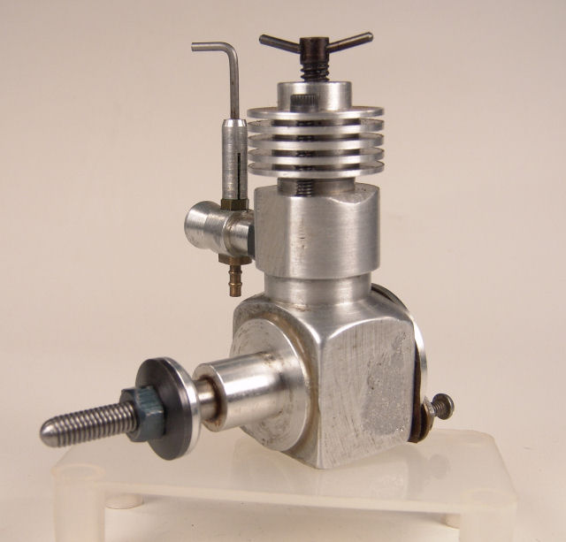
Here is a photo of Version 2. Followed by a photo or the original engine from ModelEngineNews.org so you can see some of the diffenences between Version 1 and version 2.
Imp2.jpg


imp_f.jpg


Gail in NM,USA
 
Lets start off by putting things in perspective. Because I work in the imperial system, all dimensions will be inches unless other wise specified.
The cylinder fins measure 0.875 inch (22mm) diameter and the overall height is 2.7 inch (68mm). Width over the mounting lugs is 1.375 inch (35mm). Prop shaft is 0.190 diameter threaded 10-32.
The fasteners are all either 0-80 or 2-56.
Weight is 3.1 ounces or 89 grams.

Bore is 0.313 inch (0.8mm) and stroke is 0.488 inch (12.4mm).
Displacement is 0.038 cubic inches or 0.62 cc. Thats about 1/16 the displacement of the Maryak 10 that Bob is building or 80 percent of the 0.049 engines that many of us played with as kids (and some of us still play with).

So it's oversize and overweight for it displacement. And while I don't think ANY engine is ugly, the original that this is based on comes close.
Version 2 performance was 9060 RPM with a 7-4 propeller and 10900 RPM with a 6-3 propeller. With such a long stroke to bore ratio, it will never turn a very high RPM, but it will swing a big club.

Gail in NM,USA

Edited to add displacement.
 
Gail,

Great start. :bow: and thanks for all your help with M10. :bow:

Best Regards
Bob
 
Sorry for the delay in getting started on this. Seems the big bad wolf tried to eat the bluebird of happiness, but I think all is resolved for now.

A few notes to get started with. As mentioned, there are three versions being built more or less in parallel, so some of the photos will be of different versions, so don' let it fool you. Where differences are important, I will denote the versions as V1, V2 and V3. If not mentioned, things will probably apply to all versions.

I normally work in imperial measurements, so unless other wise noted, dimensions will be in inches. The original had a mixture of BA and imperial threads. I have used all imperial threads.

For openers, here is the general arrangement drawing as extracted from the plans. It is reproduced here with permission of Ron Chernich of modelenginenews.org. The plans for this engine are published by Ron on his website. They are available free to members of his site or are available from him for US$ 15 mailed anywhere in the world. The plans are 5 sheets of letter size (ANSI A).
Gail in NM,USA


impdwgjpg.jpg

 
On most of my model aircraft style engines I start with the crankcase. Then I start adding parts to it as they are made so I can see it to start looking like an engine. This build is no exception.

I started by saw cutting 6061 alumninum for the 3 crankcases and then milling to the maximum dimensions of the 3 crankcases. The height and depth are the same< 1.667 X 0.773) for all three engines, but the width is 1.0 for V1 and 1.375 for V2 and 3. The extra width is to accomodate the mounting lugs.

Crankcase1.jpg


All the crankcases were then drilled and bored for the front bearing and rear covers. I first drilled all with a 1/2 inch drill, and then rough bored all to .740 diameter. Each was then finish bored to 0.750 inch diameter. The original was 0.756 inch diameter, but as it was not critical excepting for the mating parts I reduced it to a standard fractional size.

Not visible in the photo is that I marked the upper right corner for registration so I could return the parts to my fixed vice stops with out having to indicate the parts in for the following operations.

Crankcase2.jpg


On V2 and V3 six mounting screw holes for both the front bearing and rear cover were center drilled, drilled and tapped 0-80. Four on each side would have be adequate but I liked the look of six. On V1, only two 4-40 holes were drilled on the rear of the crankcase and the front side was left plain. On the plans, the holes were 6BA. No holes were used on the front as the front bearing will be glued in place as was the original. While this seems a little crude, several different brands of engines used this techinque during this era and I don't know of any problems resulting from it. Key was a close fit between the crankcase and front bearing and a fairly large surface area for the glue.

Crankcase3.jpg


Gail in NM,USA
 
Before continuing, a brief bit about the machine tools I use. My milling machine is a ancient Bridgeport CNC. For this project, I used it in a manual mode for all but two operations. The CNC mode was not necessary for either, but was more convenient at the time. My lathe is an import tool room lathe with a DRO. 11 inch swing and 19 inches between centers. I normally use collets on it. I do have 3 and 4 jaw chucks for it, but rarely use them. None of this is important except it determines my style of machining.

The next operations on the crankcase are to reduce the upper portion to a "double D" shape and putting a 7/16 hole from the top to intersect with the 3/4 hole. I did this operation using the CNC mill, but it could be just as easily done in the lathe using a 4 jaw chuck.

First the top was milled to an 0.85 diameter with two flats remaining from the 0.773 depth of the blank.

Crankcase4.jpg


While still set up, the 7/16 hole was drilled and reamed. This hole needs to have a good finish as the cylinder liner will fit in it. The liner needs to be a close fit to minimize leakage around the liner from the intake and exhaust ports to each other and to the crankcase lower cavity.

Crankcase5.jpg


Crankcase6.jpg


At the same setup, but not photographed, I center drilled, drilled and tapped the holes for the cylinder head mounting bolts. V1 has 2 4-40 holes to substitute for the 2 6BA holes on the original. V2 and V3 have 4 2-56 holes, only because 2 holes just looks wrong. These holes can be seen in the second and third photographs as they were put in before the 7/16 hole was put in.
Gail in NM,USA

 
Only one operation left on the crankcase of V1. Drilling and tapping the port opening for the fuel intake assembly and the opening for the exhaust. On the original, the exhaust opening was just a 1/4 inch drilled hole matching the port openings on the cylinder. I elected to tap this hole also to permit a short exhaust pipe for cosmetic purposes. The same operations are also done on V2 and V3. At this point V2 and V3 crankcases become different as the exhaust and intake are reversed. The exhaust hole ia about 0.10 inches higher than the intake hole. The positioning of these holes is not critical as the actual timing is controlled by the port holes in the cylinder, so these holes just need to cover these small holes.

I did deviate from the original a little bit. On the original, the intake hole was threaded 1/4-32. I have a 1/4-32 tap, but I like fine threads and since I had a 1/4-40 tap and die also I changed to 1/4-32. If someone were to be building this engine and did not have either, I would recommend that they stay with the original 1/4-32 as this is a common size thread for a lot on model engineering parts, in particular glow plugs and small spark plugs. It is also sometimes used for small steam fittings.

Lookng at the photo, you can see that I spotfaced the surface on the curved side with a 3/8 diameter end mill so the nut would have a smooth surface to seat on.
Gail in NM,USA


Crankcase7.jpg

 
Gail,

It's coming along very nicely. :bow: :bow:

Best Regards
Bob
 
KVOM,
The plate you see in the photos above is a 15 X 21 X 1 piece of MIC6 ground tooling plate that is bolted to the table. The vices are bolted to it. Beyond the tooling plate on each side are pieces of 1/16 sheet aluminum to keep chips out of the T slots. The Chick vices have 4 holes through them for bolts and 2 precision holes in the bottom for location. The tooling plate has precision location holes bored to match the vices. There are 3 sets on holes spaced on 8 inch centers to take 3 vices. The plate also has 4 locating pins to fit the table so it could be removed and replaced if necessary. The photos only show 2 vices as I loaned one of them to my son. It is home again, but I have not remounted it. Since all the vice jaws are removable and can be reconfigured I can clamp anything from small parts up to 12 inch wide, and by using all three vices I can cover the 12 X 25 inch travel of the machine with only a small overhang on the outsides of the outer vices. I put the fixture plate on over 20 years ago and have never had to remove it.

Table1.jpg


Table2.jpg
 
The V2 and V3 crankcases need the mouting holes drilled in the mounting lugs and the bottom of the crankcase rounded.

The mounting holes are drilled first while it is still easy to clamp the crankcase square in the vice before the bottom is rounded. They only have to be drilled about 1/8 inch deep. Prior to drilling the holes, I milled away the material down to the top surface of the mounting lug, then drilled the holes in the same setup.

Crankcase8.jpg


I used the CNC to round the bottom of the crankcase. CNC is by no means necessary to do this. Bob shows how he rounded his Maryak 10 using a rotary table mounted vertical on his milling machine in:
http://www.homemodelenginemachinist.com/index.php?topic=3712.msg39398#msg39398
I have also rounded crankcases by planeing in the lathe using a wide parting tool mounted to cut horizontally and moving it with the carriage hand wheel.

CrankCase9.jpg


Here is short video of the CNC machining the bottom of the crankcase. When doing it this way, it should be noted that the path of the cutter is not circular. This is because the cutter path is described at being at the center of the cutter, but it is the edge of the end of the cutter that we want to move in a circular path. I did this by writing a parametric program for the CNC so the cutter path is controlled by an equation. The program is only about a dozen lines long and took about 5 minutes to write. If someone is really interested in how that is done, I will make a thread about it in the CNC section sometime.
Gail in NM,USA

[youtube=425,350]KWvmAtzbQ6I[/youtube]
 
A couple of posts back I said the V1 crankcase was done. I lied. ;D

While it is not shown on the drawings, the junction of the of the 7/16 inch and the 3/4 inch bores in the crankcase need to be relieved for clearance of the connecting rod. Rather than calculate and try to machine this clearance, it is easier to do this later after other parts have been made and assembly is started. I cut the clearance with a Dremel rotary tool using a long 3/16 diameter pear shaped cutter with an 1/8 inch shank.

Even though it will be done later, I included this step here to keep all the crankcase operations in one spot.

Crankcase10.jpg


The recess between the upper and lower part of the crankcase can be cut at any time it is convenient. As I had "turned" the upper part of the crankcase with the CNC mill, I put it in near the last of the crankcase machining and did it on the lathe. If I had turned the upper part using a 4 jaw and the lathe, I would have put it in then. The recess is purely cosmetic and the only benefit it gives is to reduce the weight. These engines are so over weight anyway that is a dubious benefit. I put it in because the original had it and anything to improve the looks of this engine is helpful.
Gail in NM,USA

Crankcase11.jpg

 
Gail,

Looking good. :bow: :bow:
Not knowing the 1st thing about CNC, I was fascinated to watch the mill in action rounding off the bottom of the crankcase.

Best Regards
Bob
 
Thanks Bob -- Glad you enjoyed the video.
Now on with the show.

With the crankcases finished it is time to either go vertical to the cylinder group or horizontal to finish up the bottom end. I decided to go horizontal.

The parts to be made are the front bearing, the crankshaft and the rear crankcase cover. The order that these parts are made in has some importance. As I intend to ream the front bearing, I have little control over the hole size. So it will be made first. Then I can turn and lap or polish the crankshaft to a nice running fit in the front bearing. Planing ahead a little more, I will want to make the connecting rod before I turn the crankpin, so only the front part of the crankshaft will be finished at this time and the crankpin wiil be turned later after the conrod is made and the crankpin can be fitted to the reamed conrod.

Two different front bearings need to be made. For V1, the flange diameter is 0.875 and has no mounting holes. For V2 and V3 the flange diameter is 0.990 and each has six 0.062 clearance holes for 0-80 screws to mount the front bearing to the crankcase. For V1 no holes are needed as the bearing is glued into the crankcase.

Starting with 1.0 diameter 6061 aluminum I turned the nose part 0.437 diameter for a length of 0.562. The original had a much shorter note section, but I wanted more bearing surface, and this gave a little more conventional look to the engine. The end was chamfered about 0.015 at 45 degrees.

For the bearings for V2 and V3, a skim cut was made t0 reduce the 1 inch diameter to 0.990 and the edge was chamfered slightly with a file. Then the blank was parted off to an overall length of 0.900. This left 0.025 inch to cleanup on the cutoff end for a finished length of 0.875.

For the V1 bearing, everything was identical except the 0.99 dimension became 0.875.

Gail in NM,USA

Bearing1.jpg


Looking great Gail!

Having run CNC machines I know the pucker power of
the rapid motions in a new program.
Nice work!

Rick


The bearing blanks are reversed in the lathe so they are held by the 0.437 diameter. It is not extremely important that they are absolutely running true, but they should be running within a few thousands indicated runout on the turned surface. I was using a known good 7/16 collet so I did not bother to check.

A skim cut was made to face the end and then the part was removed and the length measured. The part was then reinstalled and an amount equal to the measured length - 0.875 was faced off to bring the bearing to length. The face was then reduced to 0.500 diameter for a length of 0.015. This is the thrust bearing face. Then the larger diameter was reduced to 0.749 for an additional 0.204 to make a smooth fit in the crankcase. I put a small relief at the junction to the flange so the front bearing would seat on the crankcase. I put a slight chamfer on the edge of the 0.75 diameter to make sure it would start in the crankcase easily. The bearing was center drilled, drilled 0.242 (Letter C drill) and reamed with a 0.250 reamer using lots of cutting fluid. It was drilled and reamed at this stage instead of the first operation to make sure the bearing hole was centered on the 0.75 diameter and perpendicular to the crankcase seating flange.


Bearing3.jpg


Now back to the mill. Holding the part in a V block, 6 mounting holes were put in the V2 and V3 bearings and an oil groove 1/16 wide x 0.005 deep was cut in the thrust bearing face. I put all the holes in with a 0.059 drill and cut the groove with a 1/16 end mill. I aligned the groove to fall between two of the mounting holes.

On the V1 bearing, only the oil groove was necessary as there are no mounting holes.

Not visible in the photos, I filed a small notch in the edge of the 0.75 diameter in line with the oil groove. This is so I can face the notch up during assembly, and the crankshaft will obscure the passage at that time. It probably does not make any difference, but I thought the bearing might get a little more oil that way. After all oil, like other well known substances, flows down hill.

Bearing2.jpg


FrontBearing.jpg

Gail in NM,USA
 
Thanks for the comments Rick.
My Bridgeport rapids are slow at 200 ipm. My Mori Seki, which my son now has, would put the fear of all holy things in to you with it's 1800 ipm rapids. Especially when rigid tapping a series of 0-80 holes at 6000 RPM with rapids between them.
Gail in NM,USA
 
GailInNM said:
My Bridgeport rapids are slow at 200 ipm. My Mori Seki, which my son now has, would put the fear of all holy things in to you with it's 1800 ipm rapids. Especially when rigid tapping a series of 0-80 holes at 6000 RPM with rapids between them.

Don't tell me any more please, my heart can't take it. :eek: :eek:
 
While I still had the 1 inch bar stock in the lathe I turned and parted off the backplates for V2 and V3. They are a simple top hat shape with 0.990 diameter for the brim of the hat and 0.750 top of the hat to fit in the crankcase. Later they were chucked on the 0.750 diameter and the back faced off and a recess bored to reduce weight. Then the mounting holes were drilled in the mill.
BackplateV2V3.jpg
BackplateV2V3-2.jpg


Although not done until later, the backplate for V1 was made the same way. On the original, the backplate was same as the the V2 and V3 backplates, but only two mounting holes were drilled for 6BA clearance. Since the engine also mounted with these same holes, the backplate was just clamped between the crankcase and the bulkhead that the engine was mounted to. Did I mention that the original was a little bit crude??

In defense of the manufacturer, they did offer an optional backplate that bolted to the crankcase and was large enough to radial mount the engine to a bulkhead from the front. I chose that option for V1. It is 1.5 inch diameter and the flange is thicker so the bolts mounting to the crankcase can be recessed. It is interesting to note that there are 4 mounting holes, but only 3 of them can be used. The 4th hole is covered up by the crankcase so there is no way to insert a bolt in it. That is the way the original was made so I put all 4 holes in mine.
Gail in NM,USA

BackplateV1.jpg


Latest posts

Back
Top