- Joined
- Feb 17, 2008
- Messages
- 2,326
- Reaction score
- 440
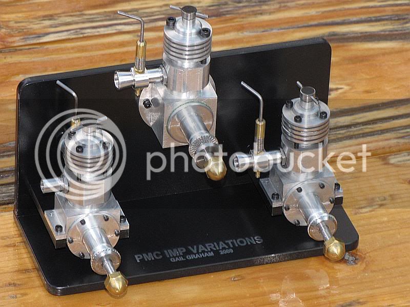
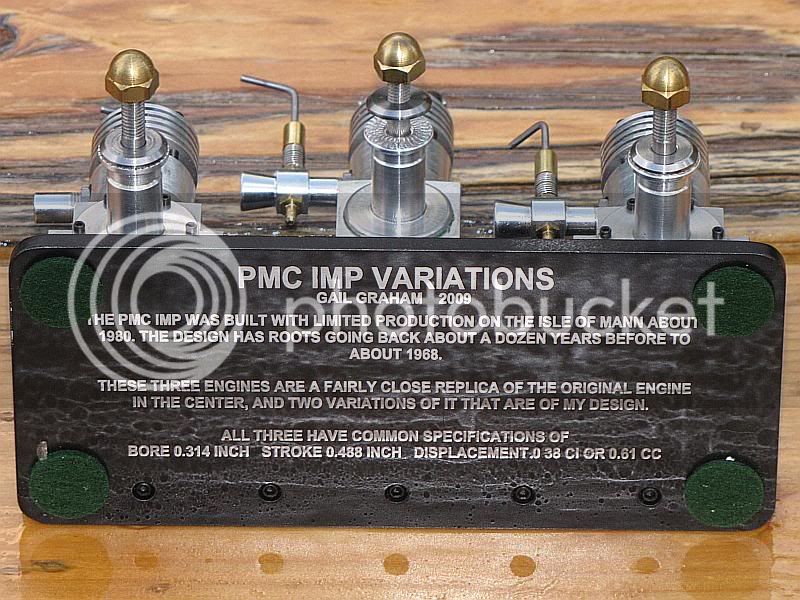
Thanks for the kind comments CC, Arnold, Diymania and Tony.
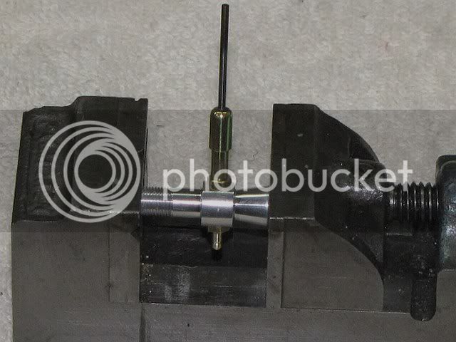
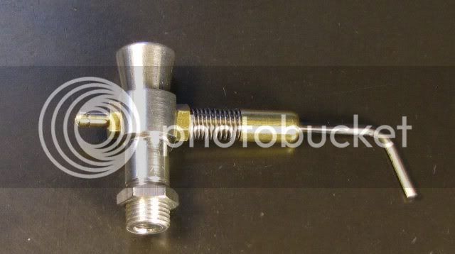
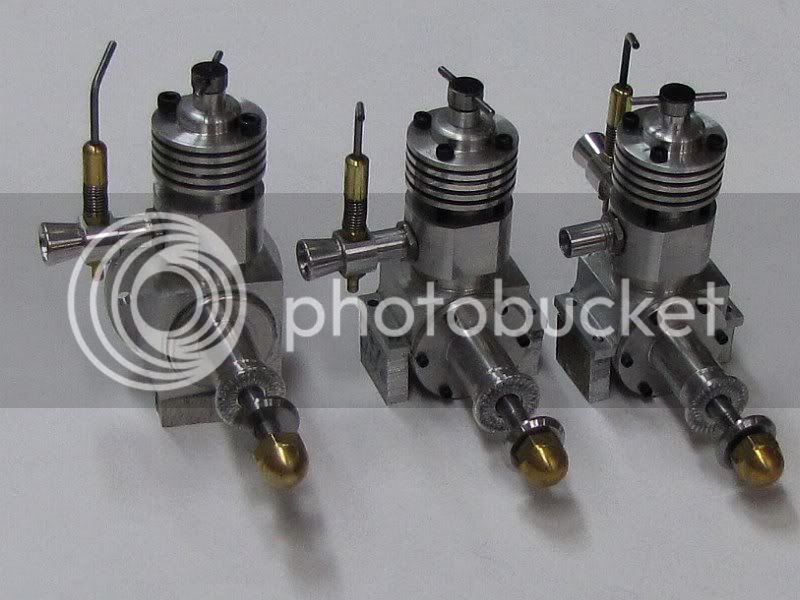
Next up is the needle parts. There are two parts for the needle. The needle and the barrel that holds the needle. Lets start with the barrel.
The barrel is just a length of 3/16 brass a little over a half inch long with 5-40 internal threads in most of it, and a 1/16 hole in the rest. About half of it is turned down to 0.14 inch for the spring to slip over. After facing the end of the rod, I turned wond the end for about 0.281. Center drilled and drilled with at tap drill for the 5-40 to a depth of about 7/16 inch. Then drilled an additional 1/8 inch with a 1/16 diameter drill. Tapped as deep as I could with a plug tap.
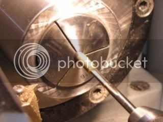
Cut the barrel off to length plus a little bit to clean up. Reversed the barrel in the chuck and faced it off and rounded the end a little bit with a file.
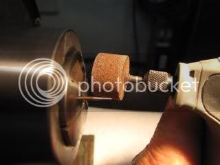
The needle is a short length of straight 1/16 music wire with a 1/4 inch long taper ground on one end. When finished it does not need a sharp point, but I find it easier to grind it to a sharp point and then to blunt the point to about 0.015 diameter. Eyeball accuracy is close enough for all these dimensions. I use a Dremel (rotary tool) with a 3/4 inch fine grinding wheel to do the grinding.
The first step is to dress the grinding wheel if it has never been dressed. A new wheel will have runout and a rough surface. If it is not dressed, the needle will have a rough surface, and probably be egg shaped from the grinding wheel bouncing. I use a single point diamond dresser that I use for my other grinders to dress the wheel. I hand guide the wheel over the dresser, holding the Dremel in one hand and the dresser in the other. To steady my movements, I rest both arms on the workbench or outdoors on the picnic table. Eye/face protection is a must, either safety glasses or preferably a face shield. Don't do this near your machine tools as the dust created is pure abrasive.
I put the music wire in a 1/16 collet on the lathe with about 1/2 inch protruding. Cover the lathe bed with a paper towel. For safety and other reasons, don't use a cloth rag. I run the lathe at about 1200 RPM. It works best if the lathe is run in reverse so the wire and the wheel are turning into each other. It gives a little smother finish, but is not absolutely necessary. I first ground a blunt taper on the end of the wire. If the end of the wire is not uniform, then the shallow taper will not be concentric when it is ground.Then the shallow 1/4 inch long taper is ground. It only takes light pressure and by moving the tool along the axis of the wire as it is being ground a very smooth finish is produced. I grind for about 5 seconds at a time to prevent overheating the wire and destroying the temper. Then let it cool for one or two seconds. It takes less than a minute to grind the taper. I ground to a point and then blunted the point. After extending the wire about an inch from the chuck I polished the ground section with a bit of 800 grit abrasive paper and polished up section of wire above the point taper so it would solder easier during assembly.
Last step is to throw away the paper towel covering the lathe ways so I don't wipe something down with it by accident.
Gail in NM,USA
Next up is the needle parts. There are two parts for the needle. The needle and the barrel that holds the needle. Lets start with the barrel.
The barrel is just a length of 3/16 brass a little over a half inch long with 5-40 internal threads in most of it, and a 1/16 hole in the rest. About half of it is turned down to 0.14 inch for the spring to slip over. After facing the end of the rod, I turned wond the end for about 0.281. Center drilled and drilled with at tap drill for the 5-40 to a depth of about 7/16 inch. Then drilled an additional 1/8 inch with a 1/16 diameter drill. Tapped as deep as I could with a plug tap.
Cut the barrel off to length plus a little bit to clean up. Reversed the barrel in the chuck and faced it off and rounded the end a little bit with a file.
The needle is a short length of straight 1/16 music wire with a 1/4 inch long taper ground on one end. When finished it does not need a sharp point, but I find it easier to grind it to a sharp point and then to blunt the point to about 0.015 diameter. Eyeball accuracy is close enough for all these dimensions. I use a Dremel (rotary tool) with a 3/4 inch fine grinding wheel to do the grinding.
The first step is to dress the grinding wheel if it has never been dressed. A new wheel will have runout and a rough surface. If it is not dressed, the needle will have a rough surface, and probably be egg shaped from the grinding wheel bouncing. I use a single point diamond dresser that I use for my other grinders to dress the wheel. I hand guide the wheel over the dresser, holding the Dremel in one hand and the dresser in the other. To steady my movements, I rest both arms on the workbench or outdoors on the picnic table. Eye/face protection is a must, either safety glasses or preferably a face shield. Don't do this near your machine tools as the dust created is pure abrasive.
I put the music wire in a 1/16 collet on the lathe with about 1/2 inch protruding. Cover the lathe bed with a paper towel. For safety and other reasons, don't use a cloth rag. I run the lathe at about 1200 RPM. It works best if the lathe is run in reverse so the wire and the wheel are turning into each other. It gives a little smother finish, but is not absolutely necessary. I first ground a blunt taper on the end of the wire. If the end of the wire is not uniform, then the shallow taper will not be concentric when it is ground.Then the shallow 1/4 inch long taper is ground. It only takes light pressure and by moving the tool along the axis of the wire as it is being ground a very smooth finish is produced. I grind for about 5 seconds at a time to prevent overheating the wire and destroying the temper. Then let it cool for one or two seconds. It takes less than a minute to grind the taper. I ground to a point and then blunted the point. After extending the wire about an inch from the chuck I polished the ground section with a bit of 800 grit abrasive paper and polished up section of wire above the point taper so it would solder easier during assembly.
Last step is to throw away the paper towel covering the lathe ways so I don't wipe something down with it by accident.
Gail in NM,USA
") - And it is good to know about the elevation issue for when I build an IC engine one day; Windhoek is also 1600m elevation.
- And it is good to know about the elevation issue for when I build an IC engine one day; Windhoek is also 1600m elevation.