PMC IMP Build log and WIP

Home Model Engine Machinist Forum

Help Support Home Model Engine Machinist Forum:

This site may earn a commission from merchant affiliate links, including eBay, Amazon, and others.
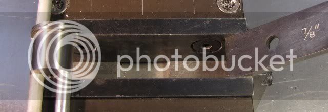
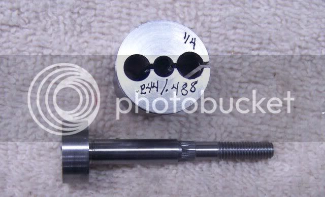
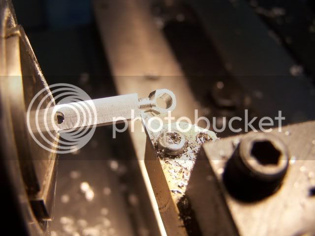
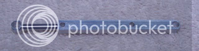
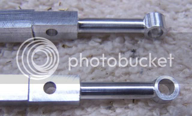
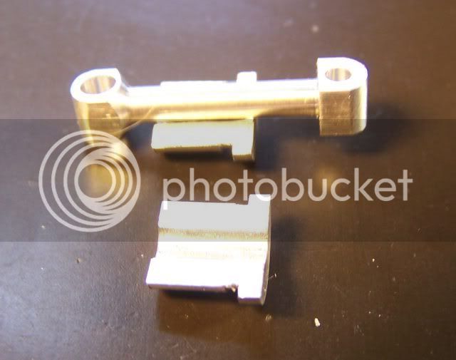
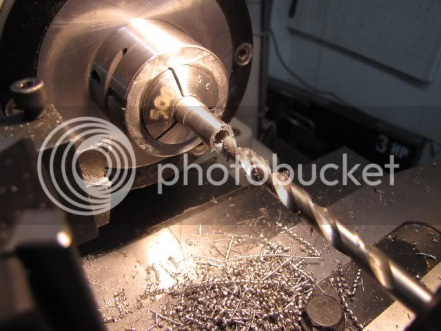
On to the crankshaft. Before starting, I drilled and reamed a 1/8 inch hole in a scrap of the same material I will be using for the connecting rod. This is just to give a check gage for the crankpin when it is turned. I could have made the connecting rods first as they are an indepentent part, but I was anxious to make the crankshaft.

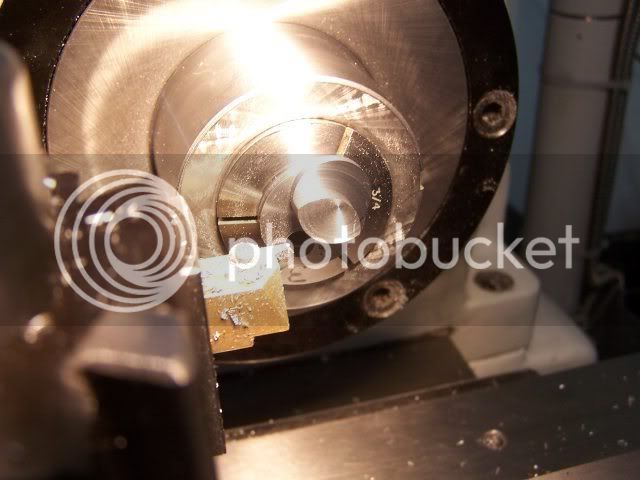
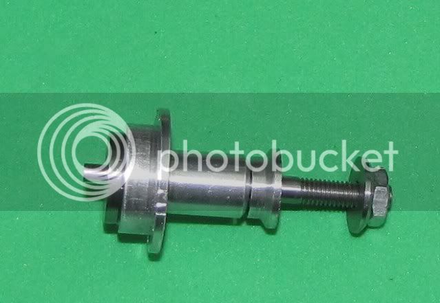
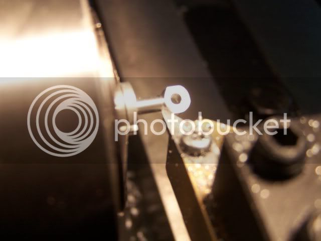
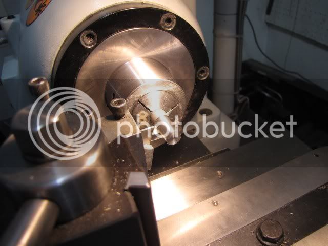
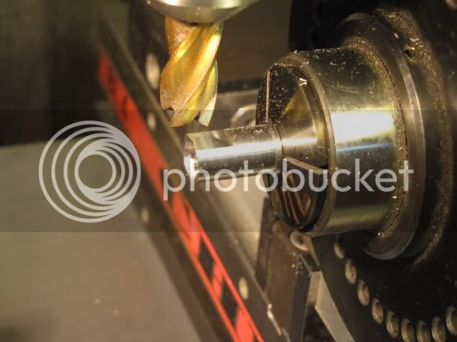
I started by chucking a length of 5/8 inch diameter 12L14 in the lathe with enough protruding to cut the from the crankdisk to the front end of the shaft. After facing the end, the 0.188 (3/16) diameter for the propeller mounting shaft was roughed to about 0.02 oversize and the bearing area was roughed to about 3/8 diameter. The reason for roughing these first is to get rid of the stressed skin that most cold rolled material has. If the bearing area was not roughed before finish turning the prop shaft, there is a good chance that the shaft will warp a little bit when the bearing area is turned. I used a VBMT 35 degree carbide insert with a 0.015 tip radius for all turning operations. After roughing, I put a 60 degree center hole in the end of the shaft and finish turned the prop bearing area. I did not find it necessary to use a center during any turning operations, but the center is still necessary to be able to use a gear puller to remove the prop driver if/when the finished engineis disassembled.


CrankShaft1.jpg


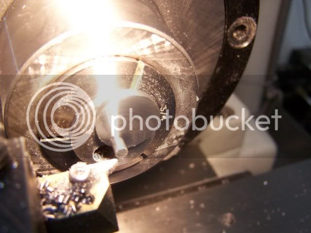
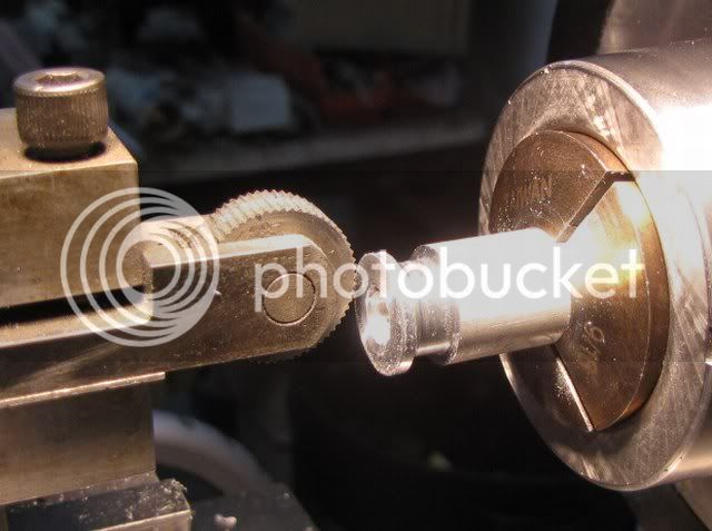
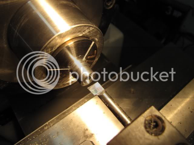
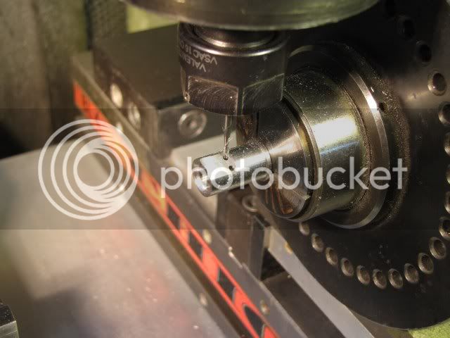
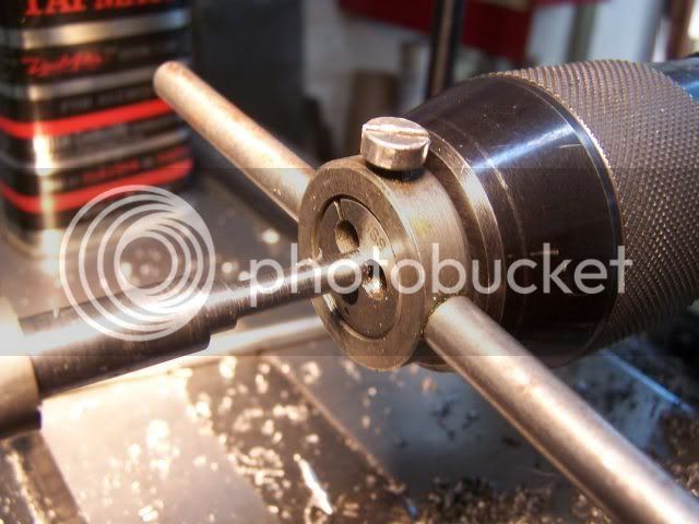
After the propshaft was turned, an additional section 0.156 long was turned to 0.203 diameter for the for the propdriver. The end of the shaft was chamfered at 45 degrees so the die would start true and the propshaft was threaded 10-32 using a die. The die was started true by applying pressure with the tailstock drill chuck. The chuck was opened so the jaws were inside the chuck body and pressure applied with the tailstock hand wheel while the first 4 or 5 turns of the thread were formed.

CrankShaft2.jpg


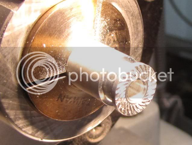
Not photographed, the area of the prop driver was lightly knurled with a single wheel straight knurl to raise the diameter to about 0.206. This probably should have been done before the finish turning of the propshaft because of the pressure of the knurling tool, but as it was a light knurl there was no bending of the shaft. This is a deviation from the drawings as the original used a taper on the shaft and a mating taper on the prop driver. Both work, so it is just a matter of preference and my being lazy.

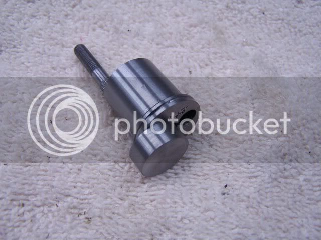
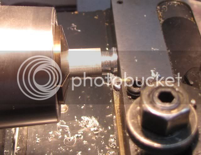
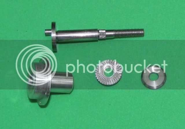
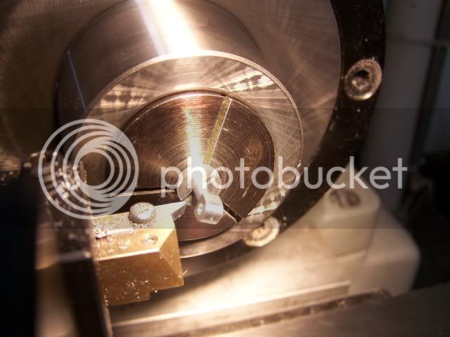
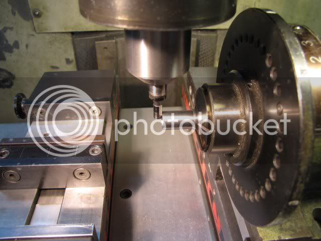
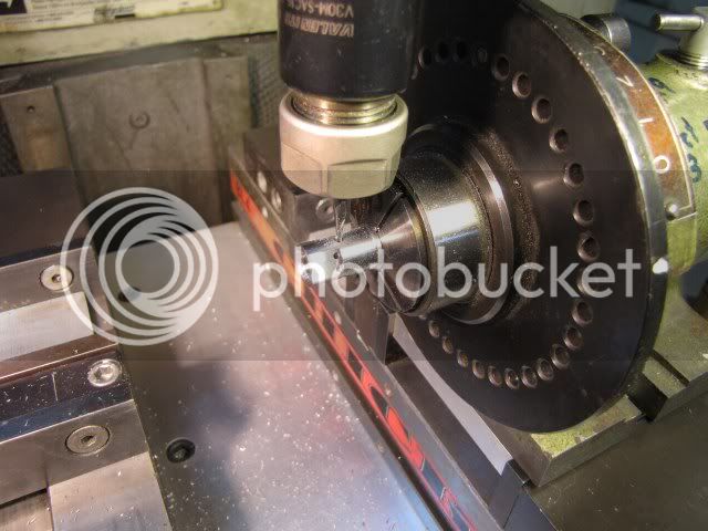
The 0.250 diameter for the bearing was finish turned and at the junction of the of the bearing and the crankdisk the tool was fed in about 0.012 to form a radiused recess. This is to make sure the crankdisk can seat on the thrust bearing. The thrust bearing could have been recessed to accomplish the same results. In either method it is important that a radius be formed at the junction of the crankdisk and the shaft to help prevent stress cracks from forming at the junction. On a larger engine I would relieve the bearing rather than the shaft.

After forming the radius, I faced off the front of the crankdisk and polished it so it would run smoothly on the thrust bearing.

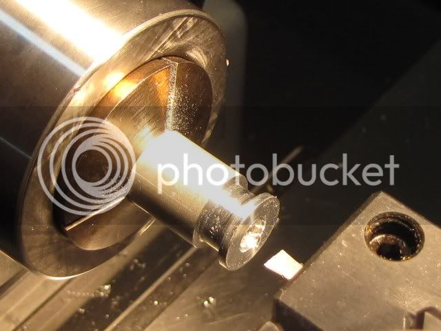
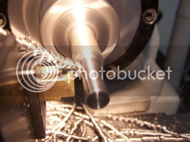
While turning the bearing surface of the shaft, I checked for a slightly tight fit of the crankshaft in the front bearing and then polished the crankshaft with abrasive paper starting with 600 grit and graduating up to 1200 grit using light oil.

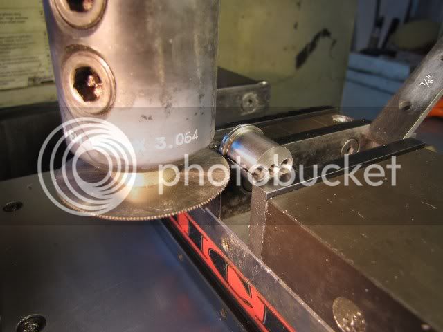
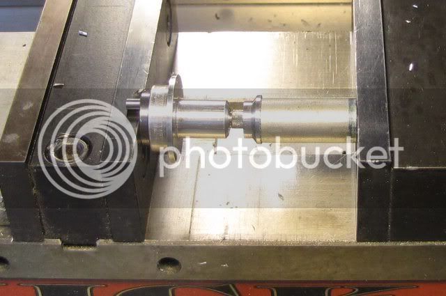
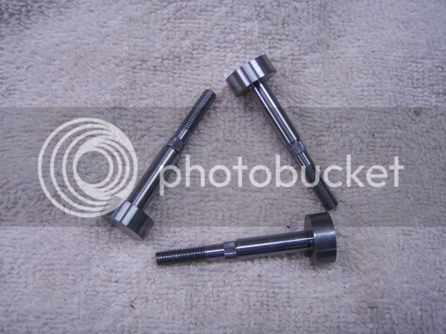
The crankshaft was fed out of the chuck to allow the crankdisk section to be polished a little bit and then cutoff with sufficient allowance for the crankpin to be turned.

CrankShaft3.jpg


Gail in NM,USA
 
Nice work Gail, :bow: :bow:

You sure don't mess around.

Best Regards
Bob
 
Before turning the crankpin, I made a fixture to hold the crankshaft. Crankpins are often turned by offseting the crankshaft in a 4 jaw chuck and that will work as well. I chose to make a fixture as I am making 3 crankshafts so it is quicker to make the fixture than to set up the 4 jaw three times. There is also less chance of damage to the bearing surface ot the chrakshaft. For me, an additional advantage is that I can use the fixture in a collet and not have to mount the 4 jaw.

I started off with 7/8 inch diameter 12L14 steel rod. Faced the end of the rod and then turned down 3/4 inch of it to a diameter of 3/4 inch. I put a relief at the end ot the 3/4 in long so the fixture would sit in the collet with out any danger of the collet gripping on the radius formed by the cutting tool. I trued up an additional 3/16 inch of the 7/8 diameter to make sure it was concentric with the 3/4 diameter and put a finger nail groove in it about 1/16 inch from the end of the 3/4 section. Just makes it easier to remove from the collet. a 3/16 hole was drilled for 7/8 depth plus a little bit and the fixture parted off a little over 7/8 inch long.

Reversing the part in the lathe, the cutoff end was then faced to make the fixture 7/8 inch long and sharp edges removed with a fine file.

I moved the part to a vee block in the milling machine, located the center using a dial test indicator in the 3/16 hole and zeroed the DRO.

Then the fixture was center drilled, drilled 0.244 (Letter C) and reamed to 1/4 inch in two locations, each 0.244 from the center and opposite each other from the center.

After removing the fixture from the vice, two rods of the same diameter and a little under 1/4 inch were inserted in the 1/4 inch holes. These rods were placed on the vice jaws and the fixture was clamped on the ends at the end of the vice jaws. Since I was clamping off center in the vice, a 7/8 inch parallel was inserted in the vice jaws at the other end of the jaws. This makes sure that the part is clamped across the end faces and not just in one point. ALL vice jaws tilt a little bit when a part is clamped near the end of the jaws, so the load should be balanced.

Crankfix1.jpg


Then the rods were removed from the fixture and a slitting saw set up to cut a slot from one edge through to the hole on the far side. I used a 0.040 wide blade, but it is not critical. A blade with fewer teeth than shown is easier, but I was too lazy to change blades. I often times just cut this slot with the bandsaw. The slitting saw looks a little nicer, but really does not do anything for the function of the fixture. It takes very little more time to use the slitting saw.

Crankfix2.jpg


To finish up the fixture, I deburred all the edges of of the slot with a fine file and marked the fixture with the dimensions of the hole and the offset. I have quite a collection of these fixtures and they get reused on occasion. I used an acid etching pen to mark this fixture, but some times I engrave them with a vibrating engraver.
Gail in NM,USA
 
With the both crankshaft blanks and the crankpin turning fixture done, it is time to turn the crankpin.

After making the crankshaft blanks, I faced off the cut off end so the thickness of the large section was equal to the thickness of the crankdisk plus the length of the crankpin.

CrankShaft4.jpg


Because of the interrupted cut, many people find this intimidating. I have had a problem with it. Just don't make any sudden moves and always turn the spindle of the lathe one turn by hand before starting the spindle under power.

The crankshaft is inserted into the hole of the fixture that has a slot to the outside. I put the fixture in a 3/4 inch collet and clamped firmly. It could be put in a 3 jaw chuck but the thin wall from the unused hole means that the fixture would be rotated 10 or 20 degrees away from the point where the unused hole is nearest a jaw. This puts the slot only approximately centered between the other two jaws.

For turning, I use the same VBMT insert I used for turning the crankshaft blank. The holder I use mounts the insert with the insert rotated 3 degrees anti-clockwise (viewed from the top) from the point where the cutting edge is parallel to the work surface. This way, only the area near the point contacts the work. I start taking light cuts, about 0.020 or 0.030 deep and cut the length of the crankpin minus 0.003 to 0.005 to leave a small amount to clean up on the crankdisk after the the crankpin is turned.

CrankShaft5.jpg


CrankShaft6.jpg


After as the cutting progressed, I increased the depth of cut as the radius of the cut decreased and then finished the crankpin to be a snug fit in the test hole I had made early on with the reamer I intended to use for the connecting rods. I finished the crankpin to length and shaved the few thousands of extras length I had left on the crankdisk by cutting from the crankpin to the outisde of the crankdisk. I then finished the crankpin to a snmooth running fit on my test hole using 600 to 1200 grit abrasive paper backed with a piece of flat metal.

CrankShaft7.jpg


Gail in NM,USA
 
With the crankshaft done, only a few small parts and the bottom end of the engine can be assembled.

Needed are a prop driver, a washer and a nut. I am using commercial nuts, but will eventually make a longer acorn nut so I dont have to pack it out to use the acorn nut. The crankshaft is longer than it needs to be so a standard acorn nut will not screw on far enough. The washer is just a slice of 1/2 inch steel with with a 3/16 hole in it. I beveled the front edge for looks.

The prop driver is a little more work, but not much.

I started with 9/16 aluminum, cleaned up the end and drilled a 0.203 hole in it a 1/4 inch deep. 0.203 is the same size I turned the seat for it on the crankshaft before knurling the crankshaft. Then a pleasing profile was cut ending with a 7/16 diameter to match the front bearing.

PropDriver1.jpg


The 0.203 hole was opened up to 0.015 deep with a small boring bar to provide some relief when knurling the front face.

PropDriver2.jpg


The front face was knurled with a straight face knurling tool with a single knurl. I only went in about 0.005 inch after the knurl touched off. Different patterns can be cut by raising or lowering the knurling tool or by using a knurling wheel with that has the pattern cut at an angle.

PropDriver3.jpg


Then the driver is ready to be cut off. After cutoff, the 0.203 hole was chamfered about 0.005 deep with a countersink so it would start easy on the knurled portion of the crankshaft.

PropDriver4.jpg


Gail in NM,USA
 
Gail,
This is a great thread! Thanks for all the detail. I'm learning a lot!


Kevin
 
Thanks Kevin. It's always a problem about how much detail to include. Don't want to bore people, but want to include enough detail to be helpful. If I stray too far either way, let me know. Now on with the show.

Since all the bottom end parts are made, it's time to assemble them.

A simple tool needs to be made to press the prop driver in place. For it, I just drilled a a 0.189 hole in a short length of 1/2 diameter aluminum. Both ends were faced off so they were square. I made the length about the same a the protruding part of the crankshaft when the crankshaft was inserted into the front bearing.

CrankAssy1.jpg


The crankshaft was oiled with machine oil and inserted into the front bearing and worked back and forth a bit to distribute the oil. The prop driver was pressed on using the tool in the vice on the milling machine.

CrankAssy2.jpg


With the addition of the prop washer and a nut, the assembly is finished.

CrankAssy3.jpg


Gail in NM,USA
 
Sliding things together it now starts to look a little bit like an engine.

Assy9.jpg


ksouers said:
Gail,
This is a great thread! Thanks for all the detail. I'm learning a lot!
Kevin

Me too, thanks Gail. :bow:

Best Regards
Bob
 
Gail
What alloys are your front bearing and prop driver? I ran into galling issues on my Little Dragon when both were 6061. I learned the hard way that 2024 has better bearing properties.
RKlopp
 
RKlopp,
I used 6061 for both the front bearing and the prop driver.
I had the same problem as you with my Little Dragon. It was the hardest starting engine I have ever built and I made extensive use of an electric starter on it. Of course, once running there is no contact between the bearing and driver, but until then......

I seem to remember cleaning up the faces of the bearing and driver and inserting a thin washer of 12L14 between the two until I got the Dragon sorted out. I made a new bearing later. I was going to make a new crankshaft and bearing so I could make them longer, but by the time I got things running well I had enough of the Dragon slaying routine so I went on to another project.

Did you get your Little Dragon running OK?

Gail in NM,USA


Gail,
My Little Dragon fired up on the second or third finger flick!! Subsequent starts required the electric motor, until the thrust from the motor chewed up the bearing behind he prop driver. Like you, I've moved on, and the Little Dragon is now a "shelf queen."
RKlopp
 
Moving toward the top of the engine the connecting rod is next. On a compression ignition engine it is under a lot of stress because of the high compression ratio. On most CI model engines the compression ratio will be in the 18:1 or 20:1 range.

I made the con rod out of 2024 alumninum. It has the necessary strength and wears well on the steel crankpin and the steel wrist pin in the piston.

I started off with piece of 1/4 X 1/2 exttruded 2024 aluminum about 4 inches long. I split it in half lengthwise and milled each half down to 3/16 square. I figured that would let me make 4 rods with plenty left over to clamp on by making a rod on each end of the strip. And, if I really messed up I could get 2 more out of the center sections.

I rounded each end of each strip using the CNC mill and then drilled and reamed the holes for the crankpin and the wristpin.

The rod part was turned by chucking the 3/16 square in a collet I used a square collet, but a 17/64 round collet will also work very well if you take care to keep all the corners out of a slot in the collet. I used the right side of the insert to chamfer the rod to end transition.
Gail in NM,USA


ConRod2.jpg


ConRod1.jpg

 
Gail,

I like your conrod and the way you are making it. :bow: :bow:

Best Regards
Bob
 
After turning the main part of the rod, I reduced the width of the small end. This could have been done when I was drilling the rods, but I did not think of it then.

ConRod8.jpg


I sawed the rods to the required length plus a little bit for cleanup. To work on the small end, I made a bushing to hold on to the turned portion of the rod and cleaned up the rod to length. I roughed the radius on the end using the CNC and then finished with a file. The wristpin end of the rod was shaped using the backside of the insert. The rest of the shaping of both ends was done with a file in the lathe using the bushing to hold the rod.

Gail in NM,USA

ConRod4.jpg


ConRod5.jpg


ConRod6.jpg

 
Now for the fun parts. The cylinder,piston and contrapiston. The absolute diameter of these is not important, but the fit of these three parts to each other is very important. The smaller the engine displacement, it more important it becomes. Because of the high compression ration, approximately 18 to 1, the fit needs to be near perfect if easy starting and adequate performance is to be expected.

The cylinder is the hardest, so it is done first and then the other two parts made to fit the cylinder. On small engines, such as this, it is typical to make the cylinder with a parallel bore in the upper part of the piston travel, and to taper the bore a small amount toward the bottom. This lets the piston move freely when it is below the exhaust ports and then almost jam in the cylinder in the compression area. Different builders have differing opinions about where this "pinch point" should be.

On this engine, I use 12L14 steel for the cylinder and cast iron for the piston and contrapiston.

I started by turning the lower portion of the cylinder up to the locating flanged and cleaning out the radius left by the toolbit with a square parting tool.

Cyl1.jpg


The cylinder is then drilled about 0.015 inch under the finished size and parted off.

Cyl2.jpg
.

Gripping on the just turned section, the cylinder is faced to length and the upper part of the cylinder is turned to diameter and again the radius is cleaned out as on the lower part.

The cylinder is bored to about 0.0015 to 0.002 under the desired finished size. I bored to 0.311 for a finished size of 5/16 inch or 0.3125. The amount of stock left is dependent on how good a finish I am getting on the boring operation. I use a solid carbide boring bar and although the photo does not show it, I use lots of cutting oil. If the finish is good, it takes a lot less time to lap the cylinder to get the desired finish.

Cyl3.jpg


This ends the lathe operations for now. Next it is off to the milling machine.
Gail in NM,USA
 
As usual, I lied. Before moving on to the mill, I put a countersink in the bottom end of the cylinder. The original had a deep narrow angle chamfer to clear the connecting rod, but as that serves no useful purpose, I shortened the cylinder and only put a small countersink in. It reduces the primary compression a little bit, but not enough to matter.
Gail in NM,USA
 
Moving over to the milling machine, it is time to mill away part of the bottom end of the cylinder to provide a passage from the crankcase to the transfer port, and drill the ports. There are three ports. The transfer port to transfer the fuel-air charge into the cylinder from the crankcase, the intake port to draw air into the crankcase when the piston is at the top of its stroke, and the exhaust that is uncovered when the piston is at the bottom of the stroke.

Each port consists of two holes drilled on a radial to the cylinder. Two holes are used instead of one big hole or a slot so the wrist pin in the piston is in contact with the the bridge between the two hole in the cylinder as it passes by a port.

Because I am building three engines and the port orentation is different, it would seem logical that two different cylinders would need to be made. The difference is that the exhaust port is on the opposite side of the cylinder on one version. I took the simple way out and put exhaust ports on both sides of the cylinder. The unused port is blocked by the crankcase, so it has no effect on the operation of the engine. It also lets me have the option of having two exhaust ports on V3 of the engine. I have not decided if I am going to do this or not. I think it would look better, but would not do anything for the engine performance.

Starting off, I mounted a 5C Spindex on the milling machine. I have modified my Spindex so it mounts in the vice with a keyed subplate on the Spindex. This way it is already parallel to the X axis of the milling machine.

The cylinder is gripped on the top end in a collet and is indicated in with an edge finder in both the X and Y directions.

Cyl4.jpg


With the Spindex set at zero degrees, the transfer passage was milled into the end of the cylinder.

Cyl5.jpg


The X position set to the location of the transfer port and the Spindex is set at Plus and Minus 22 degrees for drilling the transfer port holes.

I used a 1/16 end mill to drill the transfer port holes. I use an endmill as the holes are starting on a slanted surface and produces less burr on the inside of the cylinder.

Cyl7.jpg


The spindex is indexed 180 degrees and then offset plus and minus 22 degrees and the intake port holes are drilled with the 1/16 end mill. Of course the X position of the table is changed as the intake port is closer to the bottom of the cylinder.

The endmill was changed to a 3/32 end mill to drill the exhaust ports and after setting the X position to the exhaust port position. The Spindex was set at 90 degrees plus and minus 25 degrees and the holes drilled and then again at 270 degrees and repeated.

Cyl8.jpg


After removing the cylinder, the bore was deburred with a piece of 400 grit wet or dry abrasive paper wrapped around a 1/4 inch diameter rod. This is to prevent burrs from damaging the lap when lapping is started. Any burrs on the outside of the cylinder are also removed with 400 grit paper.

Gail in NM,USA
 
Gail,

Very nice work, you seem to be very well equipped with small tools and cutters. :bow: :bow:

Best Regards
Bob
 
Thanks Bob,
I have built mostly small toys for 50 years, so I have had lots of time to collect small stuff. Most of my machine tools are standard size however. There have been some adaptations to assist in making small parts on some of them. I would love to build a Nano class engine (0.1 cc) but I doubt that the eyes and certain body extremities would be up to it any more. At 0.6 cc, the IMP will be the last of the small displacement engines that I build and future engines will be one cc or above per cylinder.
Gail in NM,USA
 
Back
Top