
You are using an out of date browser. It may not display this or other websites correctly.
You should upgrade or use an alternative browser.
You should upgrade or use an alternative browser.
Philp Duclos "Victorian" IC engine Project
- Thread starter Cedge
- Start date


Help Support Home Model Engine Machinist Forum:
This site may earn a commission from merchant affiliate
links, including eBay, Amazon, and others.
Cedge
It has been a while since I last read of your progress, and have just managed to catch up on how you are making out with your project. Like everyone else, I am in awe of the quality of the work.
One question about the laping: You are using a 5/8" copper tube as the lap in a 3/4" bore. What did you do to get a good fit with the tube in the bore? Would you mind please explaining your lapping process for the dunces around here.
Dave
The Emerald Isle
It has been a while since I last read of your progress, and have just managed to catch up on how you are making out with your project. Like everyone else, I am in awe of the quality of the work.
Cedge said:... lapping the bore is a must. I used a softer metal for the lapping hone, in this case, copper being the metal of choice. The bore of the cylinder is .750 inches so the 5/8 copper plumbing pipe made a convenient sized lap and was long enough to give good control...
One question about the laping: You are using a 5/8" copper tube as the lap in a 3/4" bore. What did you do to get a good fit with the tube in the bore? Would you mind please explaining your lapping process for the dunces around here.
Dave
The Emerald Isle
Cedge
Well-Known Member
- Joined
- Jul 12, 2007
- Messages
- 1,730
- Reaction score
- 29
Dave
Sorry for the delay in responding... for some reason I simply missed your post. Lapping doesn't require a snug fit to work. In fact a snug fit could cause binding in the bore. I want the softer metal to make contact with the bore at a single point so that I can control the action. All the lapping is for is to remove the tiny grooves the cutting tool left, so single point contact with the polishing compound works great.
Steve
Cedge
Well-Known Member
- Joined
- Jul 12, 2007
- Messages
- 1,730
- Reaction score
- 29
I got a phone call, today, chiding me for the long silence on this thread....(grin). Worry not.... I've been steady at it, between taking care of family obligations and attending small local weekend tractor and engine shows, so without further delay....here goes.
This installment begins with a slug of rather ugly cast iron which was turned oversized to allow me a bit of room for creativity. I'm steadily drifting away from the original Victorian design, more and more, as I add small touches of my own. The critical dimensions are still those Duclos prescribed, but the devil is in the details of the final product.... as you will soon see.
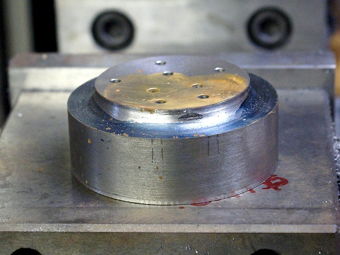
That slug of iron is the genesis for the engine's cylinder head. The first attempt went well, right up to the moment I was counter drilling flat spots to seat the acorn nuts I'd chosen to use instead of socket head bolts. I'd already completed a lot of polishing and hand finish work when I was bitten on the arse by an old adage. Measure twice and cut once. Add in the mistake of seeing one end mill with my eyes and my hand grabbing the next larger one and things went pears shaped.... real fast. I managed to open an unwanted hole directly into the combustion chamber, ruining hours of work. This is why you'll possibly notice two versions of the head in the photos.
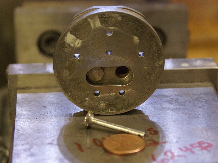
The photo below shows the head from the bottom side where the combustion chamber and the valves can be seen. The valves are 5/16 inch in diameter and 1 1/32 inches long. The seat angle is 45° and only 1/16 inch in length. Yep.... we're working tiny here. The valves were successfully lapped and the cast iron cooperated, giving me a nice tight seal. Too bad, this head would sadly die only half an hour later...(grin).
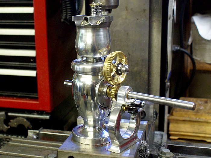
Here you see the cylinder head from the top, with the valves in place. You also get a first peek at the newly reshaped water jacket and cylinder. More on that change to he original version in a moment.
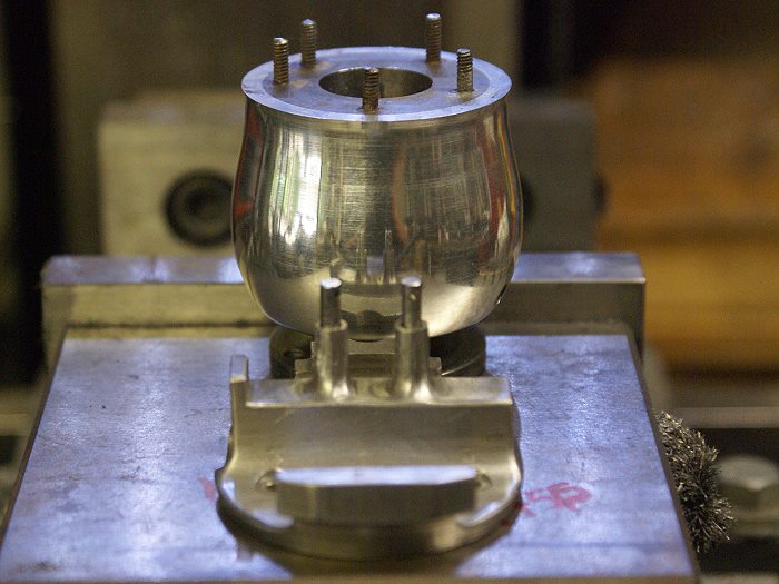
Sometimes, serendipity or perhaps, even more rarely seen, synchronicity enter the picture. The tulip contour, along with the need for a little added metal in one section of the head lead to several interesting "obstacles". The use of a ball end mill along the corners of all vertical areas also added to the fun. The Tulip shape required a bit of an under cut to the bottom edge of the head. When everything combined, the end result was a series of odd looking edge lines around the head, once it was turned back to the final dimensions.
None of this was predicted when the cutting began.... it just came to be as things progressed. The photo below shows the end results. I typically do a lot of hand filing to get the look I like, so my first thought was "no biggie... it can be filed away". As the filing began, some very nice clean flowing lines began to present themselves to my eye. They were pleasing in a natural sort of way so I began to try to figure out how to use them instead of removing them. I liked the results and they are now part of the design. No straight edges in my world...(grin)
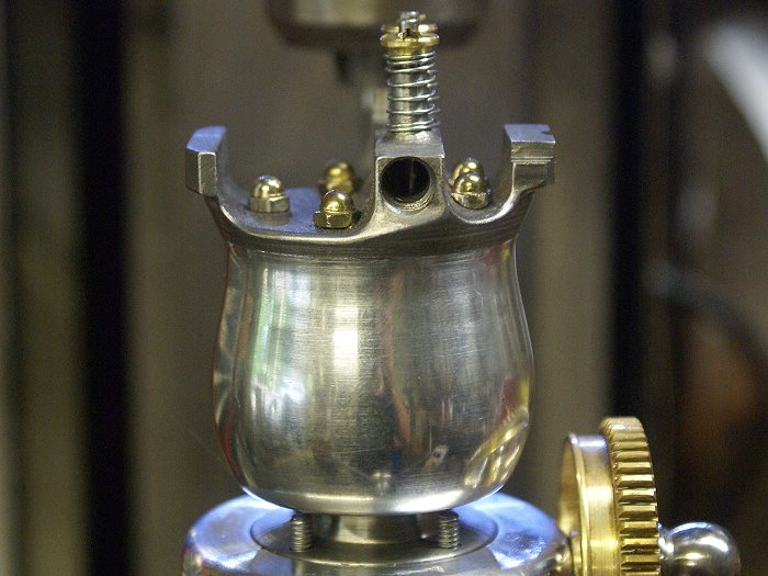
Once again, the obligatory test fit photo..... (grin). The valve springs and keepers are now in place, all the head ports are drilled or threaded and the acorn nuts are installed. The head will have a lot of brass attached to it as the carburetor, muffler, oiler and the cam roller assembly, so I toned the head down a bit after it was all polished. It received a gun blue treatment which was then lightened to a "Hematite" silver using a gentle 0000 steel wool rub. The lower neck was also given a bluing, but left darker to help highlight the tulip contour.
As I mentioned early on, this engine is destined to become "my" engine, but will remain a tribute to the skills and generosity of Philp Duclos. I dunno.... but I think he just might approve... eh?
Steve
This installment begins with a slug of rather ugly cast iron which was turned oversized to allow me a bit of room for creativity. I'm steadily drifting away from the original Victorian design, more and more, as I add small touches of my own. The critical dimensions are still those Duclos prescribed, but the devil is in the details of the final product.... as you will soon see.
That slug of iron is the genesis for the engine's cylinder head. The first attempt went well, right up to the moment I was counter drilling flat spots to seat the acorn nuts I'd chosen to use instead of socket head bolts. I'd already completed a lot of polishing and hand finish work when I was bitten on the arse by an old adage. Measure twice and cut once. Add in the mistake of seeing one end mill with my eyes and my hand grabbing the next larger one and things went pears shaped.... real fast. I managed to open an unwanted hole directly into the combustion chamber, ruining hours of work. This is why you'll possibly notice two versions of the head in the photos.
The photo below shows the head from the bottom side where the combustion chamber and the valves can be seen. The valves are 5/16 inch in diameter and 1 1/32 inches long. The seat angle is 45° and only 1/16 inch in length. Yep.... we're working tiny here. The valves were successfully lapped and the cast iron cooperated, giving me a nice tight seal. Too bad, this head would sadly die only half an hour later...(grin).
Here you see the cylinder head from the top, with the valves in place. You also get a first peek at the newly reshaped water jacket and cylinder. More on that change to he original version in a moment.
Sometimes, serendipity or perhaps, even more rarely seen, synchronicity enter the picture. The tulip contour, along with the need for a little added metal in one section of the head lead to several interesting "obstacles". The use of a ball end mill along the corners of all vertical areas also added to the fun. The Tulip shape required a bit of an under cut to the bottom edge of the head. When everything combined, the end result was a series of odd looking edge lines around the head, once it was turned back to the final dimensions.
None of this was predicted when the cutting began.... it just came to be as things progressed. The photo below shows the end results. I typically do a lot of hand filing to get the look I like, so my first thought was "no biggie... it can be filed away". As the filing began, some very nice clean flowing lines began to present themselves to my eye. They were pleasing in a natural sort of way so I began to try to figure out how to use them instead of removing them. I liked the results and they are now part of the design. No straight edges in my world...(grin)
Once again, the obligatory test fit photo..... (grin). The valve springs and keepers are now in place, all the head ports are drilled or threaded and the acorn nuts are installed. The head will have a lot of brass attached to it as the carburetor, muffler, oiler and the cam roller assembly, so I toned the head down a bit after it was all polished. It received a gun blue treatment which was then lightened to a "Hematite" silver using a gentle 0000 steel wool rub. The lower neck was also given a bluing, but left darker to help highlight the tulip contour.
As I mentioned early on, this engine is destined to become "my" engine, but will remain a tribute to the skills and generosity of Philp Duclos. I dunno.... but I think he just might approve... eh?
Steve
 th_confused0052 That is one beautiful piece of creativity that is becoming a work of art!! Holy Cow, that just rocks late 1800's. Good gosh man, I'm having brain cramps over a simple mechanism and you're generating that type of out of this world artisanship. I think I will take up another hobby, I am so envious. :toilet: BRAVO!!!!
Cheers
BC1
Jim
Cedge said:Dave
Sorry for the delay in responding... for some reason I simply missed your post. Lapping doesn't require a snug fit to work. In fact a snug fit could cause binding in the bore. I want the softer metal to make contact with the bore at a single point so that I can control the action. All the lapping is for is to remove the tiny grooves the cutting tool left, so single point contact with the polishing compound works great.
Steve
What a BFO (blinding flash of the obvious). I had never considered that a "single point" lap would work. Thanks for the tip.
Charlie
Cedge
Well-Known Member
- Joined
- Jul 12, 2007
- Messages
- 1,730
- Reaction score
- 29
Jim
Thank you for the kind words. Keep in mind that just over three years ago, I'd never even touched the dials on a machine, lathe or mill. Duclos did the heavy lifting on the design, I just added my own eye candy. I never was real good at following instructions anyway...(grin). I love this stuff and can't resist letting artistic sins, from my wayward past in the graphics and design fields, from slipping into things. There is nothing there that anyone else can't do, given patience and a slight bend in the direction of insanity.
Steve
SteveCedge said:Dave
Sorry for the delay in responding... for some reason I simply missed your post. Lapping doesn't require a snug fit to work. In fact a snug fit could cause binding in the bore. I want the softer metal to make contact with the bore at a single point so that I can control the action. All the lapping is for is to remove the tiny grooves the cutting tool left, so single point contact with the polishing compound works great.
Steve
Thanks for the info on lapping. I did not realise you could 'get away with' using such a loose fit in a cylinder for lapping. Next time I need to lap a cylinder, I'll try your loose lap method. Perhaps I had better try it on a test piece first, though!
Dave
The Emerald Isle
- Joined
- Jul 16, 2007
- Messages
- 2,987
- Reaction score
- 1,055
Absolutely outstanding work Steve. Your ingenuity just adds to this build. It's going to be one unique and beautiful engine when finished. I'm sure Phillip Duclos would heartily approve.
gbritnell
gbritnell
R
RobWilson
Guest
Hi Steve , you engine is very pleasing to the eye,great build thread, great work on those gears :bow:
This engine is going on my build list.
great work regards Rob
This engine is going on my build list.
great work regards Rob
Cedge
Well-Known Member
- Joined
- Jul 12, 2007
- Messages
- 1,730
- Reaction score
- 29
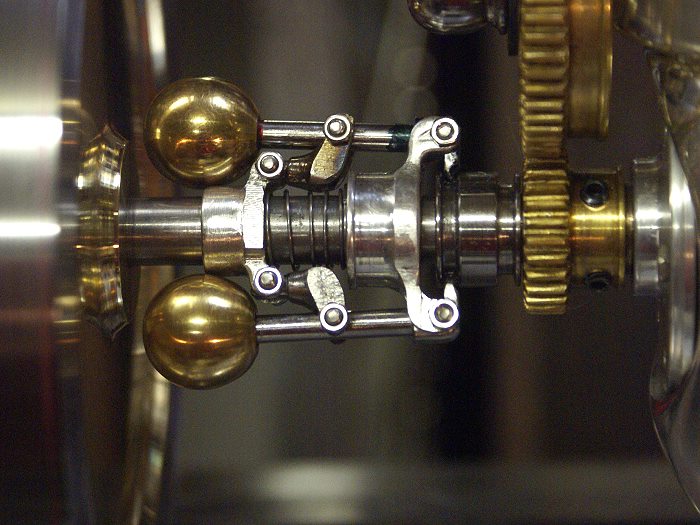
This installment deals with a re-engineering project that I'd been mentally toying with ever since the engine build began. The original design called for a very simple governor that strapped two springs to the flyballs to force them to collapse at low RPM. Functional, but with its square shafts and those springs hanging out like sore thumbs, I decided I wanted something a bit more complex and visually mechanical.
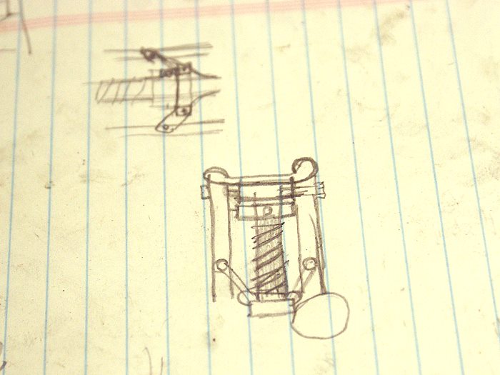
The redesign began with a pirated copy of Bogster's Crap-O-cad V.3.0 which I nabbed while he wasn't looking. This highly technical program gave me a chance to think the basics through while enjoying the fact that Bogster was out for one copy of his best...(grin). From this simple sketch, I launched off into the creative voids.
The first thought was to use a simple pair of simple straps running from the ball rods back to the lower tensioner, but space was a wee bit tight in there between the rods and the crank shaft. The connectors were finally made at a 90° so that they could fold up neatly and still allow full travel of the flyballs. When expanded, the linkage almost appears to be a small eagle with its wings spread. The spring was hand wound, but it is a shot in the dark which will probably have to be adjusted a bit once the engine is running. I made several of differing tensions to deal with that when the time come.
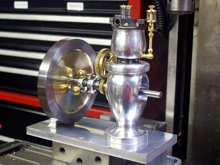
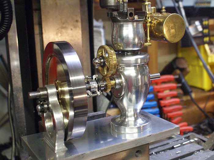
I then began the flywheel which is seen here in its first fitting. The rim is hot rolled steel which donated to the cause by Zuesrekning. Thanks Tim. The center is brass which was press fitted (.004 overlapped dimensions) using my patented 4 pound press. Can you say small sledge hammer? The final version will be a 6 curved spoke flywheel which will allow the works to be seen and contribute to the opened up look I've been chasing.
Since the first photo gave a small insight into the thought process in use, the last one will give another peek. Here the fuel tank is getting a bit of experimentation and visualization. This type of thing helps me get a better image in my head of how I will want to secure it when its time comes. The tank is a small steam engine boiler that is doing stand in duty until I've made the real deal. I had planned to use a hexagonal tank, but once it was tried out , it was immediately and definitely apparent that it was not meant for this project.
The ignition system will be ordered on Monday and the carb and exhaust muffler are yet to be built, but the project is getting closer to completion than I expected to be by now. Hopefully this one will be running before Labor Day when I'm supposed to exhibit some of my engines.
Steve
The redesign began with a pirated copy of Bogster's Crap-O-cad V.3.0 which I nabbed while he wasn't looking. This highly technical program gave me a chance to think the basics through while enjoying the fact that Bogster was out for one copy of his best...(grin). From this simple sketch, I launched off into the creative voids.
The first thought was to use a simple pair of simple straps running from the ball rods back to the lower tensioner, but space was a wee bit tight in there between the rods and the crank shaft. The connectors were finally made at a 90° so that they could fold up neatly and still allow full travel of the flyballs. When expanded, the linkage almost appears to be a small eagle with its wings spread. The spring was hand wound, but it is a shot in the dark which will probably have to be adjusted a bit once the engine is running. I made several of differing tensions to deal with that when the time come.
I then began the flywheel which is seen here in its first fitting. The rim is hot rolled steel which donated to the cause by Zuesrekning. Thanks Tim. The center is brass which was press fitted (.004 overlapped dimensions) using my patented 4 pound press. Can you say small sledge hammer? The final version will be a 6 curved spoke flywheel which will allow the works to be seen and contribute to the opened up look I've been chasing.
Since the first photo gave a small insight into the thought process in use, the last one will give another peek. Here the fuel tank is getting a bit of experimentation and visualization. This type of thing helps me get a better image in my head of how I will want to secure it when its time comes. The tank is a small steam engine boiler that is doing stand in duty until I've made the real deal. I had planned to use a hexagonal tank, but once it was tried out , it was immediately and definitely apparent that it was not meant for this project.
The ignition system will be ordered on Monday and the carb and exhaust muffler are yet to be built, but the project is getting closer to completion than I expected to be by now. Hopefully this one will be running before Labor Day when I'm supposed to exhibit some of my engines.
Steve
Thats comming along nicely, I like the governor. A more rounded tank would suit the curved feel of the engine, maybe something like the hemispherical ended tanks you get on the ball hopper engines?
Jason
Jason
zeeprogrammer
Well-Known Member
- Joined
- Mar 14, 2009
- Messages
- 3,362
- Reaction score
- 13
Awesome governor. I just stared and stared at it.
roadrage17
Well-Known Member
- Joined
- Mar 9, 2009
- Messages
- 46
- Reaction score
- 0
The only word that comes to mine is
WOOOOOOOOOOOOOOOOOOOOOOOOOOOOW
:bow: :bow: :bow: :bow: :bow: :bow:
Thats a beautiful engine
best regards
RR17
WOOOOOOOOOOOOOOOOOOOOOOOOOOOOW
:bow: :bow: :bow: :bow: :bow: :bow:
Thats a beautiful engine
best regards
RR17
Similar threads
- Replies
- 2
- Views
- 925