Philp Duclos "Victorian" IC engine Project

Home Model Engine Machinist Forum

Help Support Home Model Engine Machinist Forum:

This site may earn a commission from merchant affiliate links, including eBay, Amazon, and others.

Cedge

Well-Known Member
Joined
Jul 12, 2007
Messages
1,730
Reaction score
29
Winter is past and the shop is much more environmentally friendly, so the time is here to begin a project I've been studying ever since I bought the "Two Shop Masters" book at cabin fever. The book has plans for a number of engines, but this one caught my eye, so it jumped to the top of my build list. I've never messed with small IC engines until now so I'm curious as to how the project will go. You're invited to come a long as I attempt to take on the "Victorian", designed by the late Philip Duclos.

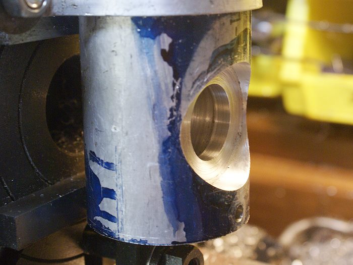
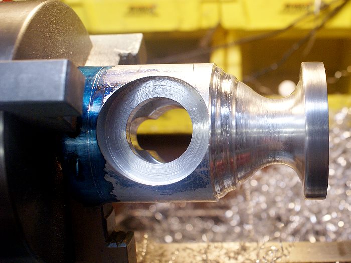
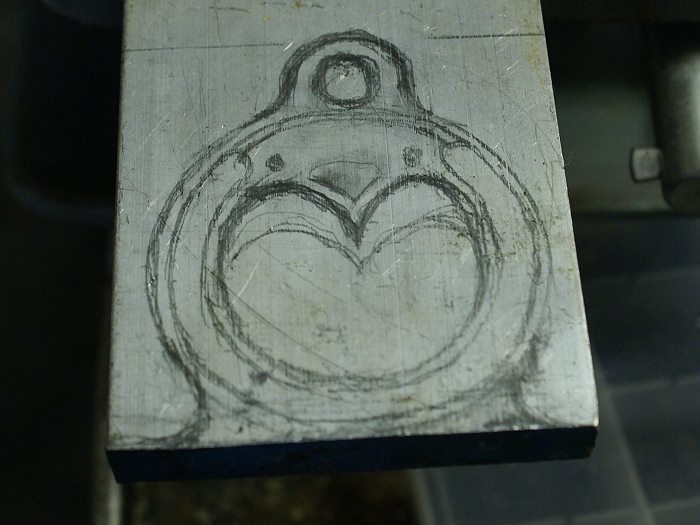
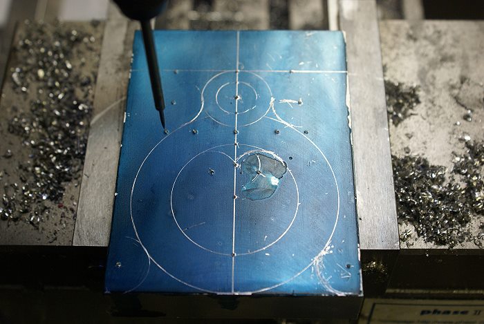
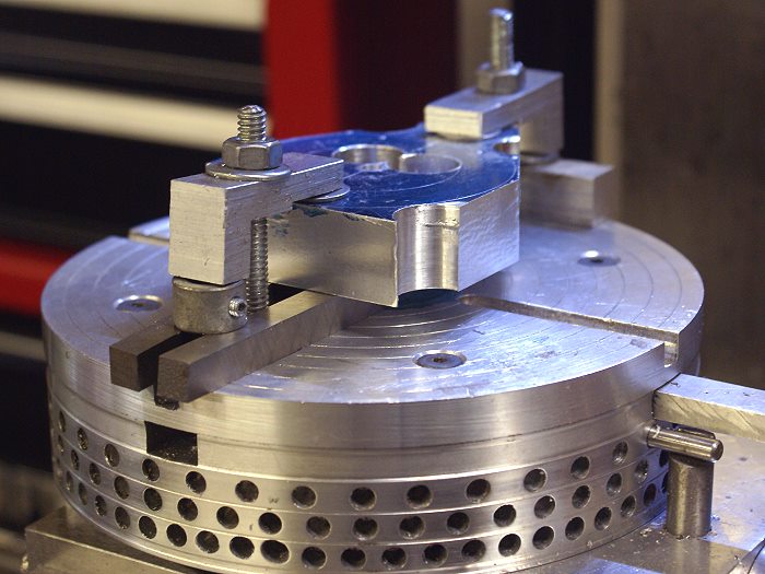
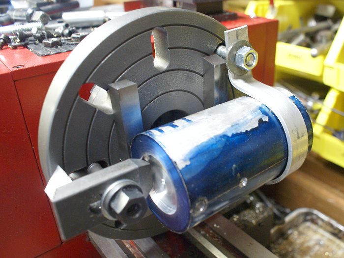
The project began with a 4 1/2 inch piece of 6061 aluminum, faced off to length and counter bored on one end. It was them moved to the mill and two flats were added to create a set of datum points for positioning the work piece as things progressed. The piece was turned over in the vise and marked for a hole which has to be bored perpendicular to the length of the work piece. once this hole was center drilled, the work piece was moved to the lathe. A threaded hole was also placed on the "back side" which was supposed to help secure the piece to a face plate when it returned to the lathe.

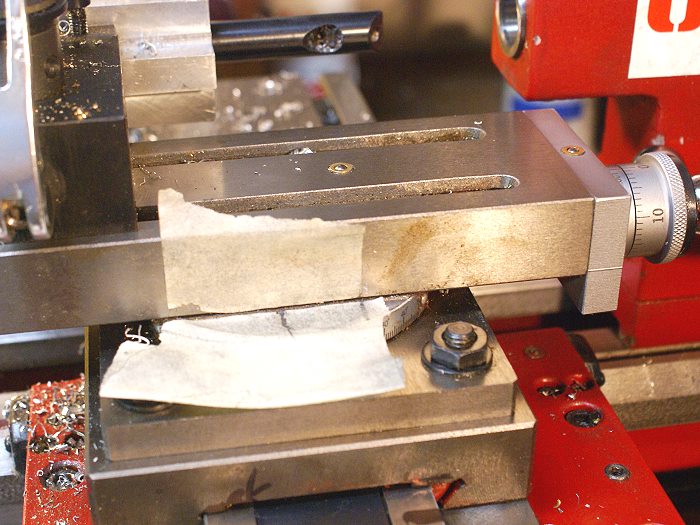
Things didn't quite work out that way due to the length of the slots in my new face plate. The bolt hole couldn't be used if the work piece was to be centered on the center drilled hole. A few minutes of head scratching was under taken and a simple strap was the solution I came up with. Not extremely elegant, but at least it worked....(grin)

setup.jpg


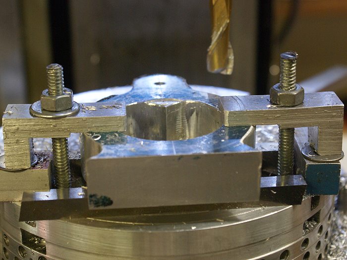
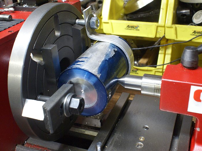
Since I only have two hands and the setup required more, I enlisted the tail stock and a dead center to help hold things while they were secured and rough centered. The dead center was fitted into the center drilled hole to get things close and to apply pressure as I was securing the work piece. This got things close, but the engine will have a crank that is suspended on both ends with close tolerance sintered brass bushings. This means things have to be dead nuts or binding will become a problem... especially since the two support points are going to be located in separate and independent components.

dead-center.jpg


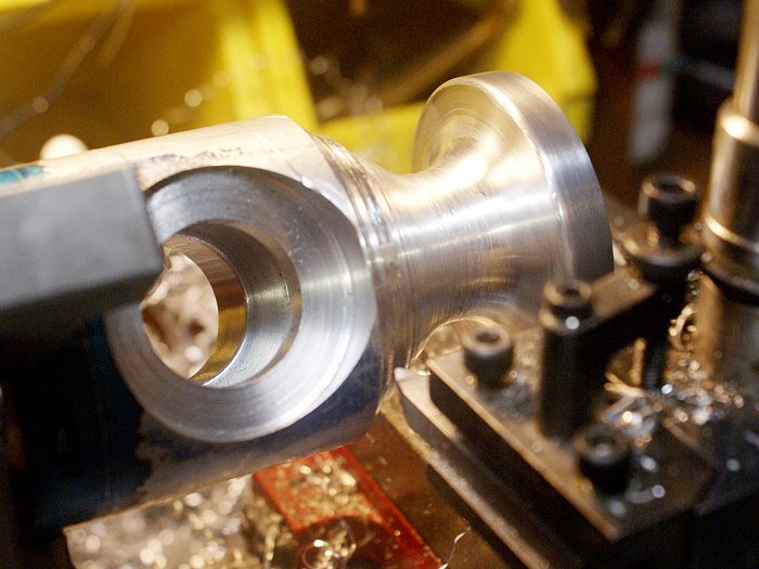
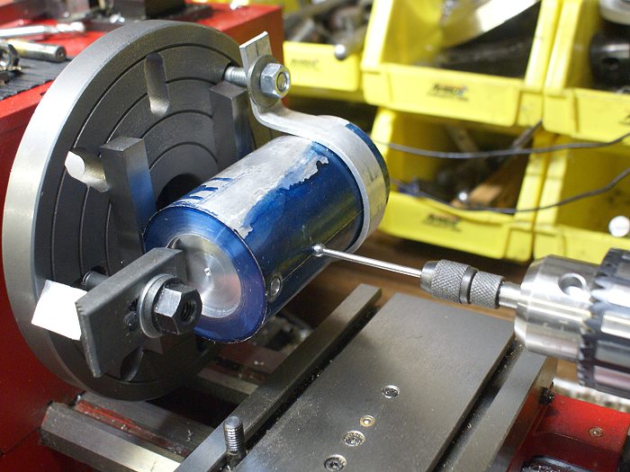
Once things were close to being centered on the center drilled hole, it was time to get everything where it needed to be. Since it is rather difficult to put a DTI on an irregular shaped object, I had to find a way to get a measure from a specific point of interest. In this case it was the center point of a somewhat tricky multiple step boring operation that has to run perpendicular through the length of the engine body.

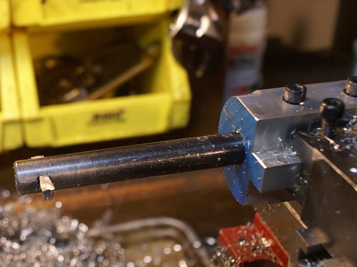
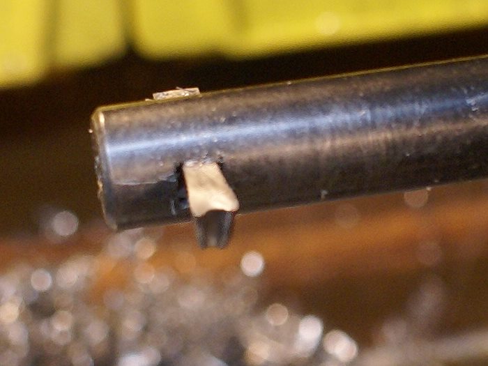
To achieve this, I employed my friendly "wiggler", mounted in the tail stock and mated to the center drilled hole. The wiggling motion gave me a fair visual reference of how far out things were, but it's almost impossible to spot which way the work piece needs to move.

wiggler-tailstock.jpg


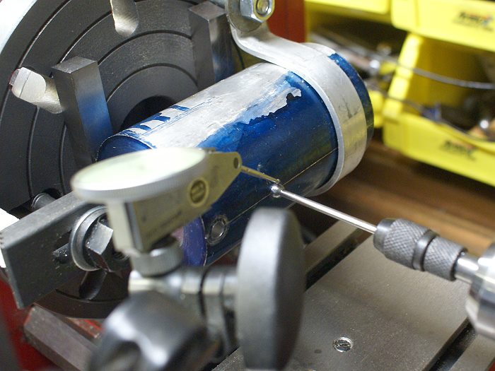
In order to get the center drilled hole perfectly centered, I used a DTI and measured the ball at the end of the wiggler. First indications were showing about .030 run total indicated run out (TIR). With a few gentle taps of the brass hammer, things quickly moved to within a couple of thousandths of the lathe centerline. The last couple of thousandths were a ticklish bit of adjustment but the final reading indicated a TIR of .0005. That should be more than close enough to work.

wiggler-dti.jpg


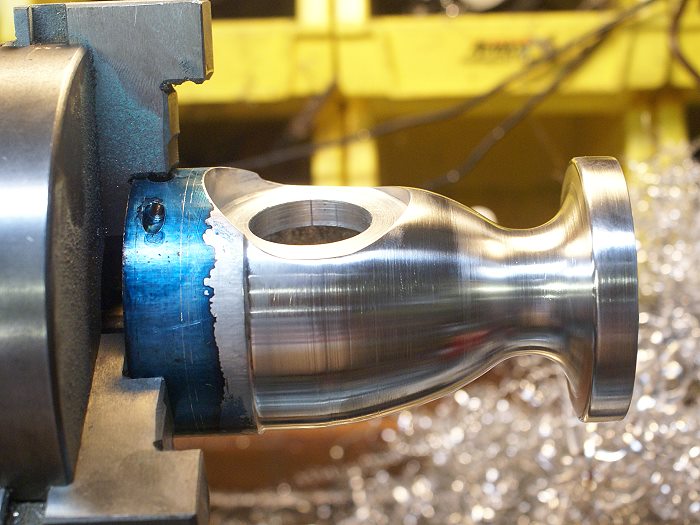
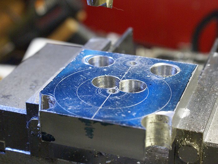
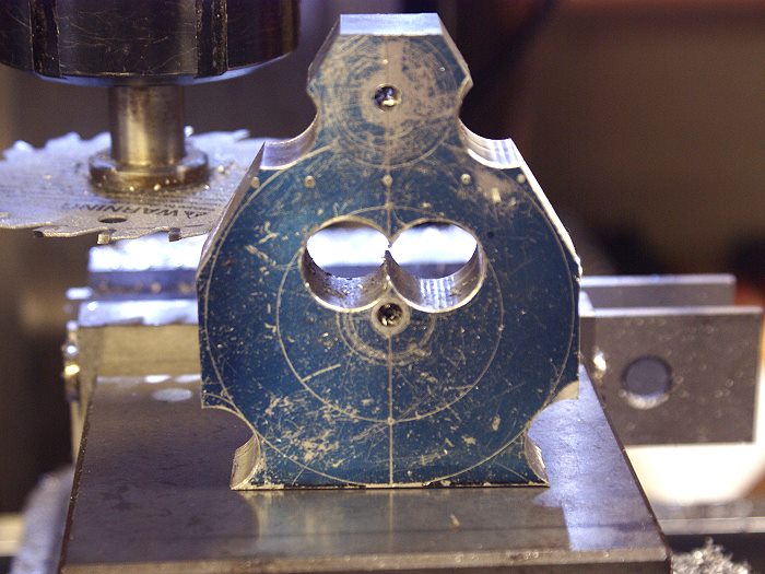
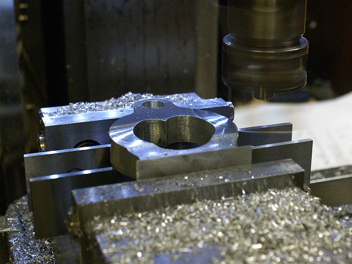
The engine body is now ready to be drilled and bored. Lots of parts yet to make, so this promises to be a long thread.

Steve
 
Hey Steve,

The Victorian is one of my favorites by Duclos. I'm anxious to see how this build goes!

Chuck
 
Steve,

I don't want to come across as a safety Nazi but I have two critiques of your setup.

I would round off the exposed square end of that strap so that, just in case, if you come in contact with it, you'll get a bump and not a laceration.

When I mount stuff to the faceplate like that, I try to arrange it such that, if things do go pear-shaped, nothing can be thrown free from the rotating plate. Instead of a block under the back of the clamp as you have, I use clamps whose riser is a bolt threaded into the back of the strap. When I do have to use blocks, I try to drill them so they can be locked down with a screw or, in extremis, a piece of safety wire or leather boot lace.

Another way to get things centered is to use the pointy end of a double-ended edge finder. This solves the problem of having a visual clue as to the direction of misalignment. (You can get a quantitative measure of the misalignment by putting a mike across the displaced parts of the edgefinder.) Even better would be a pump center with a DI bearing on it. Then you can see and measure the offset as you are correcting it.

I'll be looking forward to further details on this undertaking.
 
Hi Please excuse my ignorance but what dose the engine look like ?
Rob
 
Marv...
Concerns and advice duly noted. Unfortunately, options were somewhat limited as to what would work and still allow the face plate to turn in the clear. I'm running the setup at about 150 rpm specifically to keep things from going awry, but you can bet I'm using all three eyes while it's in motion. I'm also consciously keeping myself as far from the chuck as is possible. I've already drilled the 1.125 opening to 1" with no slippage so I need only a light boring to finish this cut. The tricky part is in the upcoming blind bore cut needed to create a larger cavity in the center of the bore. I promise... I'll use all the caution I can muster, but everything is pretty locked down and pretty stable, so it should go well.....(counting fingers yet again)

Rob....
I thought about posting a photo of the completed engine but decided not to take the chance of violating the copyright that HMS holds. The body of the engine looks almost like Grecian vase with the water cooled cylinder mounted on the top. The front has a pair of exposed gears and the flywheel and flyball governor are supported by a separate stanchion. The plans call for a rather fancy flywheel, but mine will probably be of a bit different in design. The engine is definitely an unusual design.

Steve
 
Thanks Chuck , that's a great engine design, i will have to follow this post
Cheers Rob
 
After a couple of days delay due to soccer games and a local engine show, I managed to get back in the shop today, for a few minutes.

The work piece will eventually become a contoured body for the engine which will house the crank and piston rod. This required, what was for me, a bit of a challenging bore cut. The first cut was your typical straight through bored measuring 1.125 in diameter. The outer cut will soon accept a plate with a "oilite" (sintered) bronze bushing and measures 1.8125. Neither were difficult, although the larger diameter was an interrupted cut.

The challenge came in when the third cut was made. The cut had to be centered within the work piece, it would be 15/16 inch (.9375) wide and 1.975 (1 /78) inches in diameter. OH yeah..... it would be made completely in the blind with only a couple of witness marks and the dials to guide me. NOOOOOO Sweat....right?

The delay getting back in the shop gave me time to do some mental machining and by the time I began I felt like I had a fair grip on the procedure. The photo below shows the completed cut.

bore-complete.jpg


The recently acquired boring bars offer me the ability to mount HSS cutters at 45° or at 90° and are significantly more rigid than the cheap carbide set I bought so long ago. The added plus of being able to easily adjust the cutter depth was indespensible for this particular job. The huge honking tool holder seems to help dampen vibration a bit.... even if it looks funny.

bore-bar.jpg


Yeah... the cutter does look a little odd too. Duclos suggested the strange looking end grind to reduce chatter and it really did make a noticeable difference. The sides also have a tapered cutting edge which made for encountering the side walls of the cavity with very little chatter. The double edge is there because the cutter would be running to corners in both directions of travel. The "cupid bow" end minimized tool contact and further reduced chatter. This is an idea I'll be experimenting with when doing other types of bore cuts.

bore-cutter.jpg


For those considering doing a Duclos project, be prepared to follow his instructions to the letter. After having taken on this, my second of his tutorials, it has become obvious that he has boiled procedure down to it's essence. He offers up no wasted steps and you skip one at your own peril. He makes things as easy and common sense as they can be made. Case in point....

Since the cut is being made in the blind, he suggested using tape and a couple of witness marks to keep you in control of things. He also takes you step by step while making sure you properly zero the dials, taking into consideration the adjustments to compensate for the tool size. In short, he's been there, done that and doesn't want to abuse a newbie, but he is never condescending about it.

bore-tape.jpg


From here the work piece will be transfered back the mill for a couple of steps before it comes back to the lathe for shaping.

There were some concerns about the face plate setup. It proved to be quite stable, however, I was still quite cautious about my proximity to it and the lathe was run no higher than 180 RPM to make sure it all stayed stable. This was my first time using a face plate and I must admit it won't be my last choice anymore. It certainly offers quite a wide range of possible setups. More tools in the arsenal...eh?

Steve
 
Steve,

Faint heart never won a fair lady and you've won one here :bow:, (not me, the engine). ;D

Thanks for the tip about the tool tip must try it next time I have a chatter problem.

Best Regards
Bob
 
The same tool profile is often suggested for working between the webs of crankshafts and I used it with good results.

I was doing a similar machining job at the weekend on the cylinder for my TE, there is an annulus around the liner for the steam to pass from the boiler to the regulator at the top of the casting, pic of the setup here

Jason
 
Managed to get the mill work done and then moved the engine body back to the lathe to begin shaping it. Contouring began with lots of rough cutting to get some generalized dimensions. I chose to free hand the contours, rather than sticking totally to Duclos's stylization. This proved to be an interesting exercise in both patience and eye hand coordination. To avoid any sharp edges ort corners, I used a rounded end cutter that is used for everyday roughing cuts.

As you can see.....things sometimes have to get to looking pretty bad before they get better....(grin)

contour-roughing.jpg


Here is the work piece as the foot of the engine body began to take shape. Notice the roughing cuts..... not pretty and a bit brutal, but they did move a lot of metal fast.

contour-roughing1.jpg


Here the contour of the lower half is beginning to take on its final shape. The roughing cuts were refined a bit and then I broke out the files to fine tune things. A bit of sand paper was then used to remove the file marks. The base end was contoured first since the other end will be rounded and will no longer lend itself to being chucked in the lathe. The flat surfaces of the base will chuck just fine.

contour-roughing2.jpg


Lots to do. Gears and bushings to order, a crank to turn and a platform and support to shape before I begin the upper engine section and governor. One perfect part at a time.... one perfect part at a time.... one perf....

Steve
 
Looking Great Cedge.

I've always loved that engine.

Dave
 
Today saw the engine base contouring completed and the crank bearing plate fitted. The rest of it was mostly touching up the final shape and polishing out tool marks. Not alot of excitement, but a nice feeling of accomplishment. Below are the front and rear views. If you look closely, you can also see the opening for the connecting rod in the top of the base.

Steve

contour-rear.jpg


contour-front.jpg


Holy Crap! Nice work! :bow: :bow:

Chuck
 
Steve,

Beautiful. :bow: :bow:

Oh to have even half your patience. :'(

Best Regards
Bob
 
Ok... more soccer games, mother's day and then it was back in the shop to have some more fun. The "Victorian" has a separate bearing support which is spaced some distance from the main engine body. The control mechanics, such as the governor, cam and gears occupy this space, along with the flywheel.

Duclos offered up a drawing for this support, but the engine I see in my mind's eye wanted something a little less busy while offering a clean view of the flywheel though the support. As is the case with most things I build, changes begin to creep into the design so that the finished engine is "mine". Bogstandard once brought this into focus when he told me to never doggedly follow the drawing, but to use it as a spring board. Basically, the critical dimensions are to be respected , but changes are fair game anywhere that they won't effect proper operation of the finished engine. This idea fits my creative process, so no apologies if my engine is not a "true Duclos Victorian".... eh?

The process began with several sketched ideas to test the style I'd want. I used a piece of aluminum of a similar width to that which I'd be using to machine the piece and drew my ideas with a pencil. They ranged from more complex than the original to quite a bit more simplified. The sketch shown below won out in the end. Even then it was to change in details as I watched it emerging from the metal.

support-sketch.jpg


The next step was to lay out the work piece. I did this in the vise, using the DRO and the wiggler point to locate the critical points such as the bearing location and screw holes for the ignition points. The circular lines were then marked out accommodate these points while creating the look I wanted.

support-layout.jpg


Once the mark up was complete, I used the 5/8 end mill to cut the various radii, giving me escape spaces for the smaller end mill I'd be using to cut the circular lines.

support-drilled.jpg


Since a lot of metal needed to be removed and being a bit on the lazy side, I used the carbide saw and trimmed away the excess metal. This cut down on the number of passes the cuts would require, which is more than a blessing when using a manual rotary table

support-trimmed.jpg


The center point of the main curves were drilled 3/16 to fit the dowel pins I use to index things on my handy dandy manual rotary/indexing/rounding table. After centering the table in the vise, the work piece was placed on the dowel pin and clamped down atop a two pieces of lathe tool blanks. These are ideal for use as spacers and give plenty of clearance for the end mill to penetrate or cut below the lower edge of the work.

support-rt.jpg


The photo below shows the work piece after the external and internal curves were cut. The piece is centered on the upper head of the support, where the bushing will eventually fit. Light cuts were used to keep control of things and to get the best finish possible so that final edge sanding and filing would hopefully be minimal.

support-rt1.jpg


The plans call for using 1/2 inch aluminum for the support, but one of the changes I wanted to incorporate was a flared "foot" at the bottom. I chose to use a piece of 3/4 in. metal to allow the change. Since I intend to hide the attaching screws beneath the base, there was no need to give them a flat puchase. This allowed me to use a 1/2 in radius router bit to cut a .125 deep contour at the bottom. making the edge come to a sharp edge which would easily blend into the base.

The photo below shows the piece after the contour had been cut and the flycutting operation was in progress to resize the majority of the metal to the called for 1/2 inch thickness. This process allowed me to smoothly transition from a flat surface to the flared foot with a minimum of hand work.

support-flycut.jpg


Here is the support, shown during a quick mock up to check elevations. I'll be installing the bronze bushing once the final tool mark removal is completed. You can clearly see the flare and the "foot blending" idea. It might not suit everyone, but I think this piece is a step in the right direction if I'm going to personalize the engine anyway.

support-mockup.jpg


Steve
 
I like it Steve!

I like that rotary table too....did you make that?

Dave
 
Really looking very nice Steve :bow:
Regards, Arnold
 
Steve, that piece of artful creativity just knocks me out! It has the Art Deco look about it and I think will lend itself quite nicely to the overall Victorian theme of that unusual engine. Well done, BRAVO!! Thm: :bow:

BC1
 
Back
Top