
You are using an out of date browser. It may not display this or other websites correctly.
You should upgrade or use an alternative browser.
You should upgrade or use an alternative browser.
Philp Duclos "Victorian" IC engine Project
- Thread starter Cedge
- Start date


Help Support Home Model Engine Machinist Forum:
This site may earn a commission from merchant affiliate
links, including eBay, Amazon, and others.
georgeseal
Well-Known Member
- Joined
- Jul 28, 2007
- Messages
- 105
- Reaction score
- 2
Guys,
Steve has taken a well designed engine and truly made it his own engine.
Philip would have been proud of what he has done to his design
By sticking to the orginal crictical deminisons every thing else is in Steve's words just BLING
Well Done Steve :bow: :bow: :bow:
Steve has taken a well designed engine and truly made it his own engine.
Philip would have been proud of what he has done to his design
By sticking to the orginal crictical deminisons every thing else is in Steve's words just BLING
Well Done Steve :bow: :bow: :bow:
SUPERB! is the word! Whimsical art meets function. All combined into one mans interpretation of an engine design. It absolutely knocks me out th_confused0052 to see such graceful style and mechanics so eloquently melded together. I just do not have enough words to describe what is on display here. I'm quite certain that it will run, appreciating all of the meticulous work that Steve has thrown into this project, there is no way it won't. BRAVO!!! :bow: :bow: :bow:
Bc1
Jim
Bc1
Jim
Cedge
Well-Known Member
- Joined
- Jul 12, 2007
- Messages
- 1,730
- Reaction score
- 29
Thanks guys....
George, you almost "got it" with your last post. This project was begun with the idea of making the engine "mine", but the real message is that it doesn't matter if you're building one of Elmer's, Chuck Fellow', Jan Ridder's or even a Philip Duclos engine design, you don't have to be chained to copying every move they made.
The critical measurements were faithfully followed or at least allowed for throughout this whole project. Those are the important data points that make the engine capable running when you are done. Not everyone will want to go to the extremes I've gone to with this project, but never be afraid to make cosmetic changes to your engine so that it becomes uniquely yours and different from all others in whole world.
This is not to say that I'd make such changes to a historically accurate rendition of a specific engine or fall too far from original with a casting kit, but not every engine we build need be slavishly like every other. If only one builder takes that message to heart and runs with it, this whole long thread will have been a resounding success in my mind.
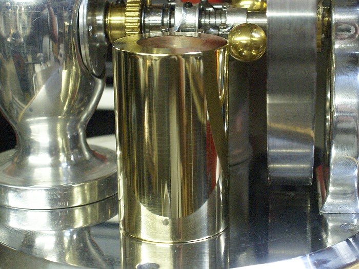
Ok... enough of the ramblings ....a few more hows are probably in order after the long gap in this thread. The cheesy little toy boiler that has been standing in for the real gas tank is now officially retired. The following photos show the beginning of the new one. This tank will be for the aspiration carb and will be replaced with a look alike once I've got time to work out the vapor tank system I want to add before all is said and done. Since my self imposed deadline is looming near, this one will have to do for now.
In the first photo, The work piece has been bored to the desired size and the first end cap has already been soldered, fitted and trimmed. I realized I needed photos just in time to share the second end cap as it was undergoing the same process.
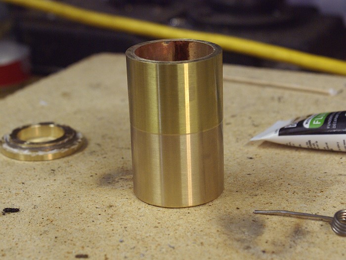
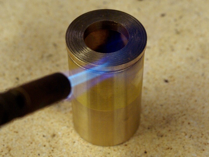
The end caps will both be fitted with a porthole sight glass, so the huge hole is not there by mistake...(grin). This one has been cleaned, fluxed and the solder is already wrapped around the center section. I flattened the solder so it could be wrapped close enough to take full advantage of the gap I left for it to fill in the bore.
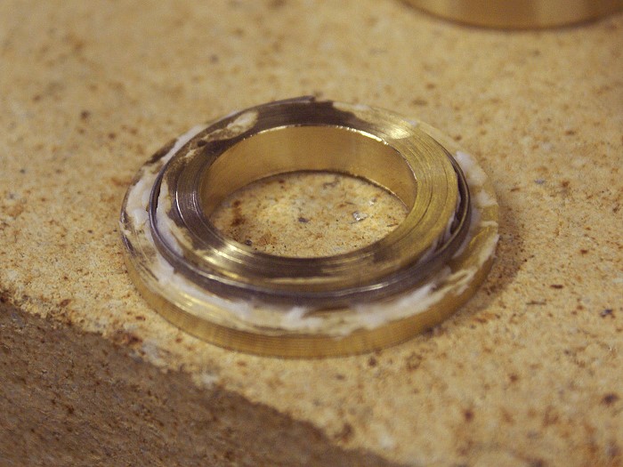
This trick also meant a much cleaner solder joint and much less clean up than trying to feed solder into the provided gap. Note there is a wide space between the two pieces. This proved to be handy as it let me see when the solder melted. As it flowed into place, the gap disappeared and the pieces mated quite close together.
Also note that the dimensions of the pieces are not final. I left some "fat" so that I could put the tank back in the lathe for clean up.
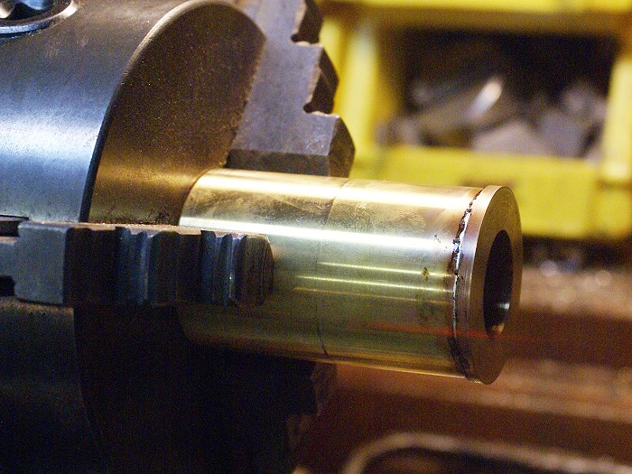
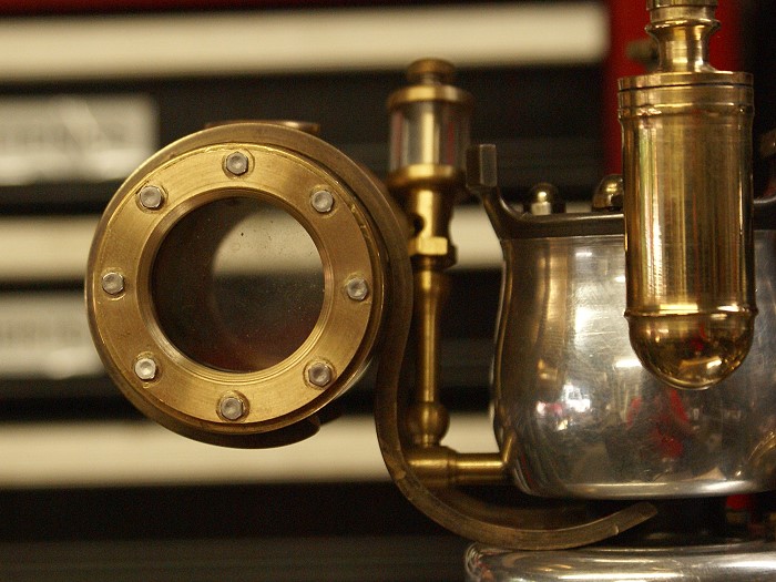
The clean up required several very light passes, but the solder lines all but completely disappeared. A bit of polishing has already begun to remove tool marks and the piece is headed back to the lathe to fit the glass, which will come in the next installment.
Here is the obligatory mock up/ test fit to see how things are going to look.
Steve

George, you almost "got it" with your last post. This project was begun with the idea of making the engine "mine", but the real message is that it doesn't matter if you're building one of Elmer's, Chuck Fellow', Jan Ridder's or even a Philip Duclos engine design, you don't have to be chained to copying every move they made.
The critical measurements were faithfully followed or at least allowed for throughout this whole project. Those are the important data points that make the engine capable running when you are done. Not everyone will want to go to the extremes I've gone to with this project, but never be afraid to make cosmetic changes to your engine so that it becomes uniquely yours and different from all others in whole world.
This is not to say that I'd make such changes to a historically accurate rendition of a specific engine or fall too far from original with a casting kit, but not every engine we build need be slavishly like every other. If only one builder takes that message to heart and runs with it, this whole long thread will have been a resounding success in my mind.
Ok... enough of the ramblings ....a few more hows are probably in order after the long gap in this thread. The cheesy little toy boiler that has been standing in for the real gas tank is now officially retired. The following photos show the beginning of the new one. This tank will be for the aspiration carb and will be replaced with a look alike once I've got time to work out the vapor tank system I want to add before all is said and done. Since my self imposed deadline is looming near, this one will have to do for now.
In the first photo, The work piece has been bored to the desired size and the first end cap has already been soldered, fitted and trimmed. I realized I needed photos just in time to share the second end cap as it was undergoing the same process.
The end caps will both be fitted with a porthole sight glass, so the huge hole is not there by mistake...(grin). This one has been cleaned, fluxed and the solder is already wrapped around the center section. I flattened the solder so it could be wrapped close enough to take full advantage of the gap I left for it to fill in the bore.
This trick also meant a much cleaner solder joint and much less clean up than trying to feed solder into the provided gap. Note there is a wide space between the two pieces. This proved to be handy as it let me see when the solder melted. As it flowed into place, the gap disappeared and the pieces mated quite close together.
Also note that the dimensions of the pieces are not final. I left some "fat" so that I could put the tank back in the lathe for clean up.
The clean up required several very light passes, but the solder lines all but completely disappeared. A bit of polishing has already begun to remove tool marks and the piece is headed back to the lathe to fit the glass, which will come in the next installment.
Here is the obligatory mock up/ test fit to see how things are going to look.
Steve
zeeprogrammer
Well-Known Member
- Joined
- Mar 14, 2009
- Messages
- 3,362
- Reaction score
- 13
Still speechless.
Very beautiful.
Very beautiful.
Cedge
Well-Known Member
- Joined
- Jul 12, 2007
- Messages
- 1,730
- Reaction score
- 29
After a short break for a busman's holiday at the beach, with all my young ones, I finally got caught back up on my sleep and hit the shop, ready to work. I'm getting the first feelings of melancholy that a project nearing its end seems to cause. I like having something to work on and I almost feel sad to see one finishing up. Anyway.... Rounding the clubhouse turn and getting ready for the sprint down the home stretch.
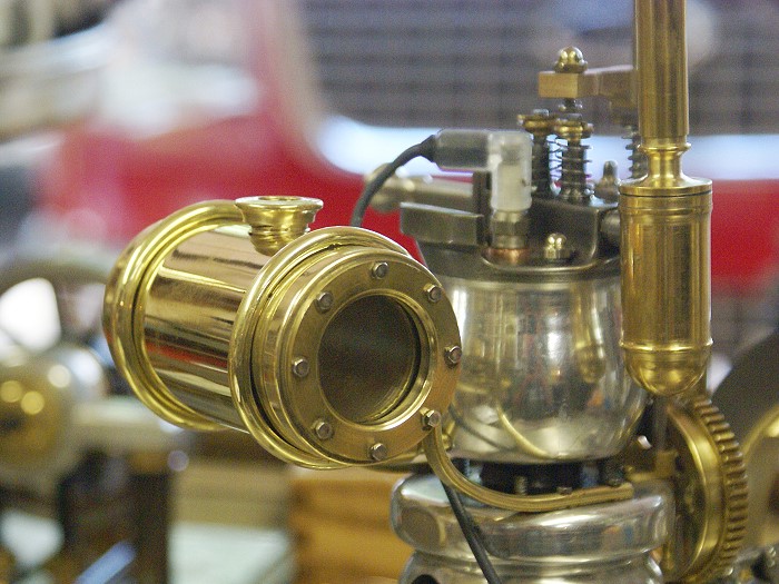
The last installment had the gas tank in its early machining stages. Since I planned to use glass ends a bit of machining to the ends was required to accept "O" rings and the glass disk. Then I had to turn up a couple of outer rings to clamp the "O" rings and glass firmly in place in order to hold the fuel.
Everything was bound not going to go perfectly, even though the 2-56 tapping went very smoothly. The first test fit found me wringing 2 of the 2-56 stainless screws off in one of the soldered ends. Note to self.... double check Z axis DRO before you begin drilling as you just might have moved the drill bit in the chuck.... Yeah he did....LOL. The DRO's proved to be worth every dime as I placed 32 bolt holes in a circular pattern with accuracy in the .00015 range.
You never know where you'll find your materials. The glass used in the tank ends came from a pair of ... oooops... three cheap watches purchased at Walmart. It's only 1/16 thick but it's tested to withstand pressure to 100 ft. They do not, however, stand up well to ham handed tightening of hex head cap screws. I managed to break the first one I installed.
The wire that has served the tank so well is now history and the supports are well on their way to getting bolted on. The 1/8 inch square brass had to be annealed before being bent to create a nice snug friction fit around the tank. The ends will bolt to the engine body and will hold the tank 1/4 inch below the carb jet to prevent siphon action, something that would cause severe flooding and an engine that doesn't run. additional bracing will be added to give the supports some added rigidity.
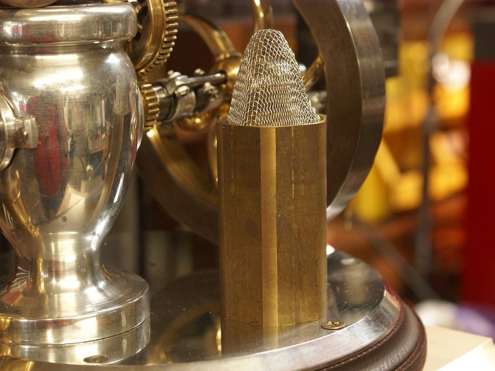
The pump has been trimmed up in preparation for fitting. Yeah... the copper wire is back in a new application, but it certainly proved handy when trying to get a look at elevations and such. The required eccentric is on tomorrow's list of projects, along with finishing the pump's end cap and the beginnings of the plumbing fittings.
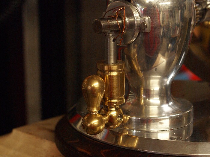
The pump has to have a water supply and the engine "needs" a means for cooling the water, so a reservoir comes in handy. The screen will act as a cooling surface as water cascades over it to air cool. The screen is from a kitchen drain strainer and was a very cheap source of stainless mesh.
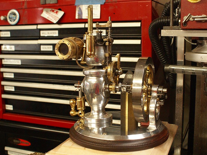
It all is beginning to come together as small details are developed. The electronics have arrived and the plug will be drilled and tapped tomorrow, as I begin tearing the engine down for wiring and final polishing. The wooden round base has already been hollowed out for the ignition system and I've begun marking out to locate the mounting holes for the engine body and the end support. It sounds as if I'm multi-tasking, but it's more like all the final steps are dependent on each other at least being there so the next can be started.
Keep those fingers crossed as this thing gets closer to its first smoke test.
Steve
The last installment had the gas tank in its early machining stages. Since I planned to use glass ends a bit of machining to the ends was required to accept "O" rings and the glass disk. Then I had to turn up a couple of outer rings to clamp the "O" rings and glass firmly in place in order to hold the fuel.
Everything was bound not going to go perfectly, even though the 2-56 tapping went very smoothly. The first test fit found me wringing 2 of the 2-56 stainless screws off in one of the soldered ends. Note to self.... double check Z axis DRO before you begin drilling as you just might have moved the drill bit in the chuck.... Yeah he did....LOL. The DRO's proved to be worth every dime as I placed 32 bolt holes in a circular pattern with accuracy in the .00015 range.
You never know where you'll find your materials. The glass used in the tank ends came from a pair of ... oooops... three cheap watches purchased at Walmart. It's only 1/16 thick but it's tested to withstand pressure to 100 ft. They do not, however, stand up well to ham handed tightening of hex head cap screws. I managed to break the first one I installed.
The wire that has served the tank so well is now history and the supports are well on their way to getting bolted on. The 1/8 inch square brass had to be annealed before being bent to create a nice snug friction fit around the tank. The ends will bolt to the engine body and will hold the tank 1/4 inch below the carb jet to prevent siphon action, something that would cause severe flooding and an engine that doesn't run. additional bracing will be added to give the supports some added rigidity.
The pump has been trimmed up in preparation for fitting. Yeah... the copper wire is back in a new application, but it certainly proved handy when trying to get a look at elevations and such. The required eccentric is on tomorrow's list of projects, along with finishing the pump's end cap and the beginnings of the plumbing fittings.
The pump has to have a water supply and the engine "needs" a means for cooling the water, so a reservoir comes in handy. The screen will act as a cooling surface as water cascades over it to air cool. The screen is from a kitchen drain strainer and was a very cheap source of stainless mesh.
It all is beginning to come together as small details are developed. The electronics have arrived and the plug will be drilled and tapped tomorrow, as I begin tearing the engine down for wiring and final polishing. The wooden round base has already been hollowed out for the ignition system and I've begun marking out to locate the mounting holes for the engine body and the end support. It sounds as if I'm multi-tasking, but it's more like all the final steps are dependent on each other at least being there so the next can be started.
Keep those fingers crossed as this thing gets closer to its first smoke test.
Steve
Engine maker
Well-Known Member
If your looking for glass ends for fuel tanks you may want to try this. Flat mineral glass watch crystals. Diameters go up by .004" to way bigger than you may care to use and thickness is 1mm, 1.5mm, 2mm, 2.5mm and 3mm. 3mm works out to be right at .120". I get them at: http://www.ofrei.com/WatchMaterials.html
You have to search around a bit to find the page to order by size instead of by brand, but look and you'll find it. I think the last time I ordered some they were 3 for $10.
Here's a pic of the Engine and tank I used them on last.
And here's the page with the thick glass listings, It's kind of hard to find
http://www.ofrei.com/thick-mineral-glass.htm
hitandmissman
Well-Known Member
That has really turned out great. I wish I had half your talent.
Man, I'm telling you that engine just screams 'circa 1800's' Victorian era. In my minds eye it captures my imagination and sends me to scenes from a Jules Verne movie aboard "The Nautilus" submarine with all of its flourishes and embellishments. Truly a wonderful piece of artistry to behold Steve. Fantastic. :bow:
BC1
Jim
BC1
Jim
Cedge
Well-Known Member
- Joined
- Jul 12, 2007
- Messages
- 1,730
- Reaction score
- 29
Guys
Your sharing in the fun has made this project a treat. I've been watching for old Jules to come calling to reclaim his property, but so far the coast is clear. The engine really has taken on a Verne-esque quality, as the small finishing details are added. I might never build another IC engine, but the one I've gotten from this project is just crazy enough to fit me and the collection to a "T". If that measure constitutes success, then it has been just that... a success.
The project has reached the point where all the work is small stuff, some tedious and delicate, some of it almost downright boring. Progress is ongoing but at a much less dramatic and slower pace.... thus the gaps in time between posts. Most of the work has been permanently mounting and fitting things, fine tuning assemblies and the delicate tweaking of parts that involves.
Since I've been pretty open in this thread, I'm almost obligated to share the very near disaster that sneaked up on my a couple of nights back. After mounting the engine to the base and making some adjustments to the 3 bearings to loosen things back up, I began the process of fine tuning the long train of components that run from the governor to the very top of the engine.
3:30 AM is not the best time to be doing things that require ones fullest attention, but then it's also a time when your judgment concerning such things is not at its highest. The engine was chucked in the lathe so I could observe the governor under power and make the needed adjustments to various parts and pieces. Part of this process required that I position the cylinder section atop the base between "running" the engine the lathe.
Everything was going fine and I'd been religiously removing the cylinder section between each test run. Then a serious case of cranial flatulence descended on me. For some reason, without thinking, I reached for the lathe's start switch and flipped it on before removing the cylinder.
Remember the cam gear? ......yeah.... the one with all the spokes and teeth and time. When the dust settled, there sat an engine with everything nice and square, with the exception of the the cam gear, which now sat at an odd angle of about 25° off plumb. The cylinder was hanging from the rear of the engine in an even more distressing angle. I'm not sure how long it took me to react, but all the the chaos was long completed, before I could even begin to move to stop it.
Now... long experience has taught me a number of things, among which is the fact that adrenalin and shock do not contribute positively to making sound decisions. As I began to untangle the damage I slowly took stock of things. I then moved the engine to my work table where I sat and stared at it until the obscene expletives ran down in my mind. Only then did I begin to run a rapid mental train of options for fixing the problems.
Luck didn't totally desert me, as it became obvious that everything was still "intact". No broken spokes were evident, but the center hub was listing badly and there was some indication that the cam ring or gear might have suffered, but only some testing would tell the tale. I began by grabbing a 5/16 transfer punch (among any shop's most versatile tools) to use as a Tommy bar. After carefully placing the gear in the mill vice, this let me gently manipulate the center hub and carefully nudge things back in position by eyeball.
I then paused and took stock of my options, once again, deciding the lathe definitely offered more potential tricks than anything else at hand. I mounted the gear on the small arbor I used during the gear cutting adventure and turned on the lathe. Things were looking up as I noted the eyeballing had been quite surprisingly effective. It wasn't perfect, but well things were well within the range of repairable, assuming I could come up with a means to push it all back into position.
Once again that mental options train left the station, as I smoked things over. If you let ideas stew long enough they tend to distill themselves and something will usually bob to the top. One of the tools I use quite a bit is a small rollerl on a bar that can be clamped in the QTCP. This tool lets me remove the wobble from work pieces that were removed and then placed back in the lathe for further work. It has the added benefit of being able to apply pressure to a work piece either from the side, or from the end, in order to bring the piece into square with the center line of the lathe. It might not be an industry acceptable text book tool, but then I've never read the book anyway.
Long story made at least a little shorter, it worked. The tool was applied to the end of the work piece and cranked it in using the compound. This quickly got the end face running square to the lathe centerline. I then moved it to side of the cam ring and, with gentle movements of the cross slide, began to remove the unwanted distortion and restore concentricity to both the gear and the cam ring. I reinstalled the gear to the engine and it ran smoothly..... not even any chattering.
There is a fair level of violence taking place when the cam actuates the exhaust linkage. As a result, I will eventually make this gear afresh so that I can shake the lack of "trust" I'm feeling. I'd rather invest the additional time and effort than chance more damage in the future, due to a failed spoke.
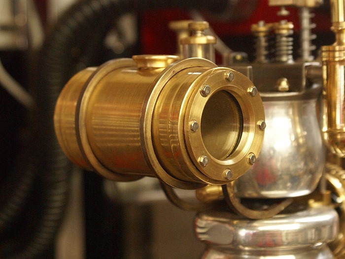
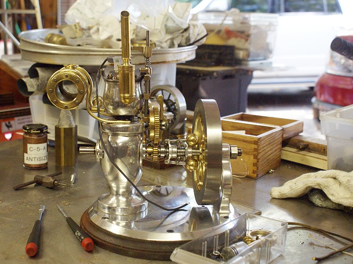
Okay...quite a long winded tale, but if you're still awake, I'll share something a bit less morbid. The tank mounts are now completed and bolted down in their final form. The square bar stock just wasn't giving me the warm fuzzies, so I'd been avoiding the final step of drilling and taping the holes to secure them. Another of those "long time experience"s thing is that when I procrastinate over something like this, for some reason, everything is not quite congealed into a final satisfying from. I've learned to let the process run its course until an idea finally surfaces that meets all the requirements. Such was the case here.
The curves were "right" but the hard lines of the bar stock were bothering me on some level. The idea finally surfaced and the solution was dead simple. I put a piece of 3/16 round stock in the mill and made up a few inches of 1/2 round brass. This formed easily and gave me a bit more grip on the tank surface while giving it all the missing curves this engine has been demanding. Once the bending, polishing and drilling was completed, the end results were what you see below.
I've still got to fabricate the filler cap and the drain that goes to the carb, but that should be only a few minutes work. The pump is in one of those "idea stews", at the moment, but is nearing its turn for my hands on attention. There is a bit of plumbing yet to be done and the electronics still have to be to fitted, but I can see light at the end of the tunnel and no trains are in sight... for now....LOL The tank definitely now adds a nice look to an already "interesting" machine.
Steve
Your sharing in the fun has made this project a treat. I've been watching for old Jules to come calling to reclaim his property, but so far the coast is clear. The engine really has taken on a Verne-esque quality, as the small finishing details are added. I might never build another IC engine, but the one I've gotten from this project is just crazy enough to fit me and the collection to a "T". If that measure constitutes success, then it has been just that... a success.
The project has reached the point where all the work is small stuff, some tedious and delicate, some of it almost downright boring. Progress is ongoing but at a much less dramatic and slower pace.... thus the gaps in time between posts. Most of the work has been permanently mounting and fitting things, fine tuning assemblies and the delicate tweaking of parts that involves.
Since I've been pretty open in this thread, I'm almost obligated to share the very near disaster that sneaked up on my a couple of nights back. After mounting the engine to the base and making some adjustments to the 3 bearings to loosen things back up, I began the process of fine tuning the long train of components that run from the governor to the very top of the engine.
3:30 AM is not the best time to be doing things that require ones fullest attention, but then it's also a time when your judgment concerning such things is not at its highest. The engine was chucked in the lathe so I could observe the governor under power and make the needed adjustments to various parts and pieces. Part of this process required that I position the cylinder section atop the base between "running" the engine the lathe.
Everything was going fine and I'd been religiously removing the cylinder section between each test run. Then a serious case of cranial flatulence descended on me. For some reason, without thinking, I reached for the lathe's start switch and flipped it on before removing the cylinder.
Remember the cam gear? ......yeah.... the one with all the spokes and teeth and time. When the dust settled, there sat an engine with everything nice and square, with the exception of the the cam gear, which now sat at an odd angle of about 25° off plumb. The cylinder was hanging from the rear of the engine in an even more distressing angle. I'm not sure how long it took me to react, but all the the chaos was long completed, before I could even begin to move to stop it.
Now... long experience has taught me a number of things, among which is the fact that adrenalin and shock do not contribute positively to making sound decisions. As I began to untangle the damage I slowly took stock of things. I then moved the engine to my work table where I sat and stared at it until the obscene expletives ran down in my mind. Only then did I begin to run a rapid mental train of options for fixing the problems.
Luck didn't totally desert me, as it became obvious that everything was still "intact". No broken spokes were evident, but the center hub was listing badly and there was some indication that the cam ring or gear might have suffered, but only some testing would tell the tale. I began by grabbing a 5/16 transfer punch (among any shop's most versatile tools) to use as a Tommy bar. After carefully placing the gear in the mill vice, this let me gently manipulate the center hub and carefully nudge things back in position by eyeball.
I then paused and took stock of my options, once again, deciding the lathe definitely offered more potential tricks than anything else at hand. I mounted the gear on the small arbor I used during the gear cutting adventure and turned on the lathe. Things were looking up as I noted the eyeballing had been quite surprisingly effective. It wasn't perfect, but well things were well within the range of repairable, assuming I could come up with a means to push it all back into position.
Once again that mental options train left the station, as I smoked things over. If you let ideas stew long enough they tend to distill themselves and something will usually bob to the top. One of the tools I use quite a bit is a small rollerl on a bar that can be clamped in the QTCP. This tool lets me remove the wobble from work pieces that were removed and then placed back in the lathe for further work. It has the added benefit of being able to apply pressure to a work piece either from the side, or from the end, in order to bring the piece into square with the center line of the lathe. It might not be an industry acceptable text book tool, but then I've never read the book anyway.
Long story made at least a little shorter, it worked. The tool was applied to the end of the work piece and cranked it in using the compound. This quickly got the end face running square to the lathe centerline. I then moved it to side of the cam ring and, with gentle movements of the cross slide, began to remove the unwanted distortion and restore concentricity to both the gear and the cam ring. I reinstalled the gear to the engine and it ran smoothly..... not even any chattering.
There is a fair level of violence taking place when the cam actuates the exhaust linkage. As a result, I will eventually make this gear afresh so that I can shake the lack of "trust" I'm feeling. I'd rather invest the additional time and effort than chance more damage in the future, due to a failed spoke.
Okay...quite a long winded tale, but if you're still awake, I'll share something a bit less morbid. The tank mounts are now completed and bolted down in their final form. The square bar stock just wasn't giving me the warm fuzzies, so I'd been avoiding the final step of drilling and taping the holes to secure them. Another of those "long time experience"s thing is that when I procrastinate over something like this, for some reason, everything is not quite congealed into a final satisfying from. I've learned to let the process run its course until an idea finally surfaces that meets all the requirements. Such was the case here.
The curves were "right" but the hard lines of the bar stock were bothering me on some level. The idea finally surfaced and the solution was dead simple. I put a piece of 3/16 round stock in the mill and made up a few inches of 1/2 round brass. This formed easily and gave me a bit more grip on the tank surface while giving it all the missing curves this engine has been demanding. Once the bending, polishing and drilling was completed, the end results were what you see below.
I've still got to fabricate the filler cap and the drain that goes to the carb, but that should be only a few minutes work. The pump is in one of those "idea stews", at the moment, but is nearing its turn for my hands on attention. There is a bit of plumbing yet to be done and the electronics still have to be to fitted, but I can see light at the end of the tunnel and no trains are in sight... for now....LOL The tank definitely now adds a nice look to an already "interesting" machine.
Steve
Good heavens man! I'm having stomach ulcers and brain spasms even thinking of the sheer terror that flashed forever in your mind in that one instant of "Oh S**t!" Not oops, or ah crap, but HOLY Saints of everlasting doodoo! Man alive, that story has given me a few more grey-ish ;D hairs. Glad to see you were able to get it all sorted out. BTW: what time DID you finally call it quits that outing? "Nah Honey, I just got up, go back to sleep" (yeah right, in a pig's end :big") It is amazing what the same lines that are curved and not square will do to ease the starkness of a part. Well done, well done indeed!
It is amazing what the same lines that are curved and not square will do to ease the starkness of a part. Well done, well done indeed!
BC1
Jim
It is amazing what the same lines that are curved and not square will do to ease the starkness of a part. Well done, well done indeed!BC1
Jim
Cedge
Well-Known Member
- Joined
- Jul 12, 2007
- Messages
- 1,730
- Reaction score
- 29
Jim
I missed seeing sunrise, but not by very much. I was back in the shop by 10:00 AM, although I did manage a couple of much needed cat naps that day. For a few seconds there I felt in distinct need of an emergency draw string replacement for my rectal orifice...LOL
I was amazed at the difference the new supports made, too. I could visualize the effect in abstract but when the metal was fitted, it was crystal clear that the engine wanted to go there. When little engine speaks.... me listen.
Steve
Similar threads
- Replies
- 2
- Views
- 895