Opposed Twin I.C.

Home Model Engine Machinist Forum

Help Support Home Model Engine Machinist Forum:

This site may earn a commission from merchant affiliate links, including eBay, Amazon, and others.
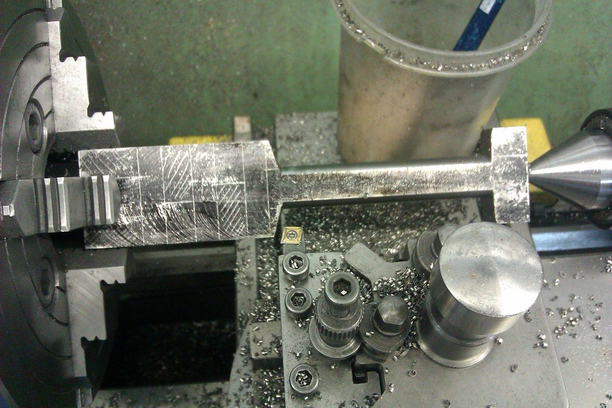
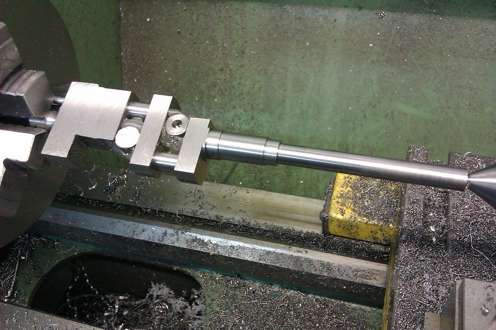
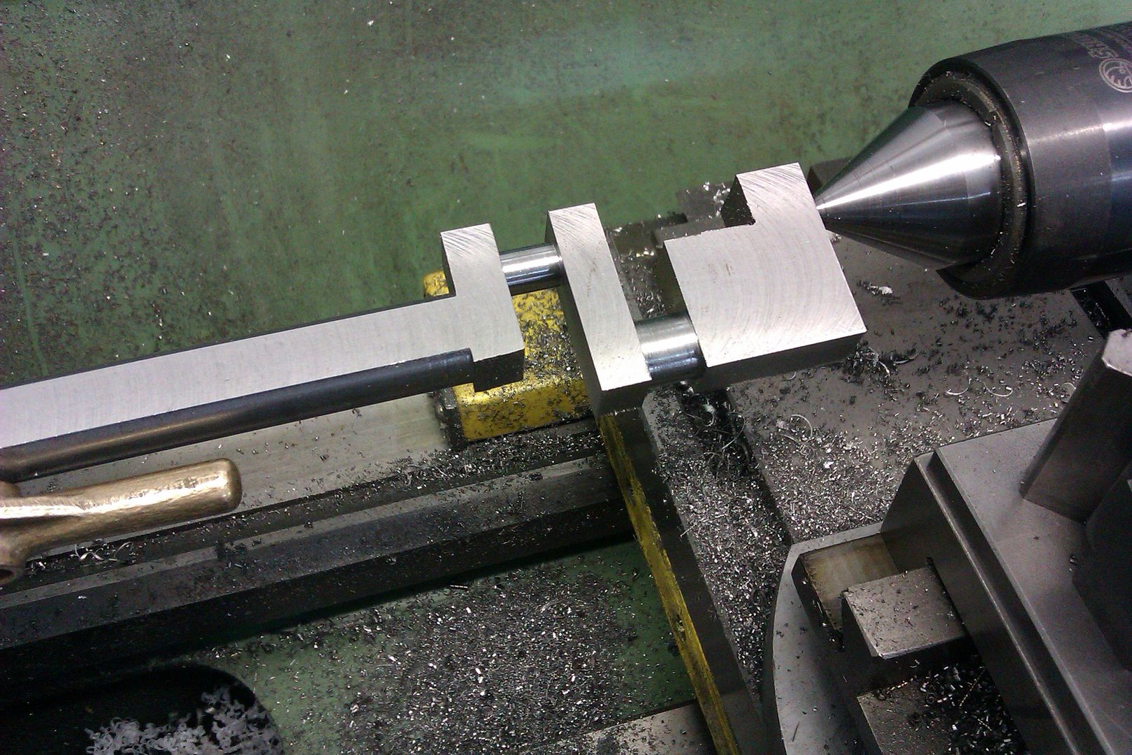
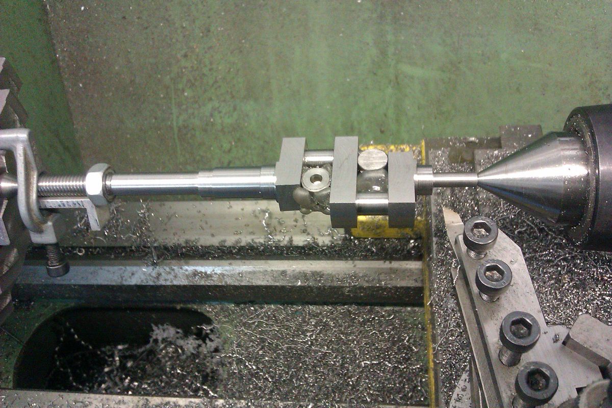
After what seemed to be far more struggle than I anticipated, the tailstock alignment is correct within .001" of being the same as the center in the headstock spindle. I ended up machining two ends of a bar held between centers and adjusting the tailstock until I was getting micrometer readings within .001" of each other at each end, and said "That's it!!!". I made a lathe dog to drive the bar that was held between centers, and was really surprised how much it threw the lathe out of balance. I would have liked to run the lathe at 800 rpm to get a really good finish on the two areas I turned, but at anything over 350 rpm the lathe wanted to levitate. I will have to add counterweights to the faceplate when I turn the crankshaft between centers using a lathe dog.
 
Okay--we forge onward here, adding to our list of what seems to work and what doesn't. I now know that the 4 jaw chuck is complete and does indeed fit the spindle. The faceplate is a beautiful thing, and it fits alright, but it throws the lathe out of balance at anything over 400 rpm., even without any lathe dog. I take it from that that the faceplate casting itself is out of balance. Changing the 3 jaw chuck (which does seem to be in balance) for the faceplate (which seems to NOT be in balance) is a pain in the arse!!!! I now see the wisdom in just chucking up a piece of roundstock and turning a 60 degree point on it to make a center at the headstock when I want to turn something between centers. Doing this will allow me to use a much shorter, and therefore more balanced lathe dog as well.
 
And here we have the latest in "Extreme low tech lathe doggery". Drill and tap one leg of a very cheap machinist clamp for a quarter inch bolt. The designer liked his fancy design, but the machinist said `Whoa---Too much work!!!` I will put a tie-wrap around the shaft and thru the arms of the machinist clamp `just in case`.
 
I will put a tie-wrap around the shaft and thru the arms of the machinist clamp `just in case`.
Hi Brian
IMHO
nice workI would have the shaft end Round and prick punch the offset and run with a dog leg

Or do what you are doing using your mill , That crank is flat Out so you can go
0,180, 0 to machine everything

nice work
 
Well---Maybe it's not up there with sky-diving, but it sure makes my old heart go "pitter-patter"!!!! I'm running at 200 rpm.--Standing well to one side of potential "flying bits". First rod journal is cut to correct width but needs a clean-up to get the diameter down from 0.430 to 0.375". Probably nothing to it for all the "old time machinists" out there, but it scares the Bejeezuz out of me.
 
I'd advise roughing out all over (leaving lugs with throw centres in at the ends, obviously) before finishing any dimension.
Charles--I hadn't really thought about that. The only problem I see with it, is that it would become very difficult to turn the ends down. I'm not even really sure how you would go about doing that unless you plunge cut with a parting off tool out at the ends.
 
Charles--I think this is what you mean. This photo was posted on another forum I post on by Jason, a gentleman from the U.K. The piece I am currently working on isn't long enough to allow for this.---Brian
 
I assume Charles suggested roughing it all out to allow for any stresses in the steel to show themselves, then final machining to size would eliminate any distortion that had occurred. As you're using 1144 stressproof it shouldn't matter. My Peewee V4 crank didn't seem to change at all as it was machined.
 
Charles--I think this is what you mean. This photo was posted on another forum I post on by Jason, a gentleman from the U.K. The piece I am currently working on isn't long enough to allow for this.
Brian, yes, that is exactly what I mean. After the crankpins are finish turned you cut the lugs off (with a hacksaw) and finish turn the main journals between centres (with distance pieces between the webs, if you like). I don't understand what you mean when you say your part is not long enough.
 
Brain you don't cut the whole of the block at the end away, just enough to leave a square that is then turned down as part of the main shaft.

This is finished length

Roughing
IMAG2895_zpsm2hrxie5.jpg


Part way through, front waste material removed and test fitting bearings, waste still on teh back end. Note ctrs also drilled and tapped so a stud can be screwed in to drive the crank against a chuck jaw

IMAG2935_zpsca4v8mxp.jpg


IMAG2930_zps9kn4tyuj.jpg


IMAG2928_zpsbnlnws1q.jpg


Finishing the other end

IMAG2940_zpsn87uitld.jpg


brian crank.jpg
 
Tomorrow morning I get to the "extreme breath holding" part of this----The "sides" of the rod journal are turned to their finished width, but I have to turn the journal diameter down to it's finished size. On my old lathe, I would have set up my "carriage stops" on both limits of travel to keep the sides of the crankshaft from whacking the top of the parting tool and creating instant disaster. On my new lathe, I don't have any real good way of setting up "travel limiters" on the topslide (Which I have set up parallel to the ways and can still thankfully advance by hand.) This will be a "Stand well to one side and move the topslide REALLY SLOWLY" sort of deal.
 
  • Like
Reactions: gus
Here we have finished rod journal #2. Everything is right on spec. and turned to final size. I have a "perfectly fitted" aluminum spacer in the gap where I cut the first journal from, to keep the crank from deforming under the pressure of the lathe "centers". It is held in place with glue from a glue gun---See---I do learn things from these forums!!! This second journal wasn't quite as scary as the first one, but you certainly don't want to let your mind wander while doing it!!! It really helps my peace of mind knowing that I actually do have a carriage lock on this lathe. (Which I just found out about this morning when I logged on and read my forum mail.) I will now glue a spacer in this new gap and then proceed to find my way through turning the ends down.
 
This morning I turned the first main crankshaft journal, and discovered a dirty little secret. I have suspected all along that it would be almost impossible to set the topslide perfectly parallel to the ways. You can get it super close with a dial indicator, but I still didn't totally trust it. I confirmed that this morning by turning the crankshaft journal down over it's full 2" length using the topslide only, with the carriage locked, but I left the journal a bit oversize. I then measured both ends with a micrometer, and sure enough, I was turning a very slight taper. Having established that, I locked the topslide and used the power feed on the carriage to take the last .025" off the diameter, to final size. That left a very nice finish, and no taper. We learn---we learn---
 
So---Here we have it, finished except for trimming the ends to get rid of the countersinks, and a keyway for the flywheel. It fits into the "engine block" just like it's supposed to. That 1144 stress-proof steel is a wonderful material. After all the machining operations involved, I put the shorter end of the crankshaft in the three jaw chuck on my lathe and put an indicator on the very far unsupported end, then rotated the chuck through 360 degrees. The total indicated runout was .003"!!! That is .0015" of "center shift". Almost unbelievable. Not only did I manage to make a nice crankshaft, but I learned some good things about using my new lathe. I'm glad it's done. I have sweat bullets this week.---Brian
 
This morning I turned the first main crankshaft journal, and discovered a dirty little secret. I have suspected all along that it would be almost impossible to set the topslide perfectly parallel to the ways. You can get it super close with a dial indicator, but I still didn't totally trust it. I confirmed that this morning by turning the crankshaft journal down over it's full 2" length using the topslide only, with the carriage locked, but I left the journal a bit oversize. I then measured both ends with a micrometer, and sure enough, I was turning a very slight taper. Having established that, I locked the topslide and used the power feed on the carriage to take the last .025" off the diameter, to final size. That left a very nice finish, and no taper. We learn---we learn---

No ones ever too old to learn new tricks 😃

Paul.
 
  • Like
Reactions: gus

Latest posts

Back
Top