Open Column Launch Engine from Kit

Home Model Engine Machinist Forum

Help Support Home Model Engine Machinist Forum:

This site may earn a commission from merchant affiliate links, including eBay, Amazon, and others.
zeeprogrammer said:
Believe me...I'm fiddling with tiny parts and wondering where did it go. ;D

But no...not this engine...it's going to be straight from the box...'kit-bashing', as the plastic modelers say, will come as I develop and learn.

Man...if I had to spend an hour...it's time for a new part...if I could.

Cheaper to spend the hour than off to the store for a replacement, Like going for just a gallon of milk, Dozen donuts, cheesecake, salami and hard roll later, and then have to turnaround to go back for the milk.

Ok, built per plan works, I gotta go get a gallon of milk :)


Don't think about shortening the reamer. You want it long so that it will efficiently seek/hit the center of the hole.
 
Zee,

Just shows the pen is mightier than the sword. ::) I'm so glad we misunderstood what you were trying to say.
smiley-signs113.gif


Best Regards
Bob
 
Telescopic gauge technique... Everybody seems to have his own technique but here's what I do.

Adjust the arms to a diameter just a bit larger than the bore, then snug down the lock screw so they stay in that position but are not locked so tightly that they can't be moved with gentle finger pressure.

Insert the thus prepared gauge into the bore. Since the gauge diameter is greater than the bore, you'll need to angle the gauge to do this. An angle of 30 or so degrees is good although this isn't particularly critical.

Now swing the arm of the gauge to align the gauge handle with the bore axis. This will force the telescoping elements into contact with the bore and compress them so their diameter matches the diameter of the bore. Try to keep the handle of the gauge centered relative to the bore while doing this so the telescoping arms can find the true diameter of the bore.

Once the gauge handle is aligned to the axis of the bore, carefully tighten the lock screw to lock the measurement. Withdraw carefully so you don't further compress the arms.

Measure gauge with a micrometer. Be very careful here. The mike has a 40 tpi thread so it has a tremendous mechanical advantage. Over-tightening it will easily compress the gauge and give a false (under) reading.

I generally take at least three readings and throw out the outlier(s) on the premise of bad technique.

If you have an inside mike, it probably came with a ring gage for setting its zero. Since this hole (in the gage) is accurately bored and lapped, it's great for practicing your telescopic gauge technique - you know what the bore must be so you can concentrate on getting the measurement.

Of course, as you undoubtedly know by now, there's no need for the cylinder to be any precise diameter since you'll make the piston to fit. In fact, there was no need to ream except for the finish that the reamer leaves behind. Boring the hole was important since boring will straighten out any irregularities left by the drills. Reamers don't straighten holes, they merely bring them to size (and usually improve finish).

Drilled holes are neither round, straight nor on size. The sequence is:
Drill to remove material.
Bore to straighten and make cylindrical.
Ream to bring to size.

Kvom is correct about reamer length. The idea is to grip the reamer by the very end of its (usually long) shaft so the tip where the cutting action occurs is free to "follow" the hole.
That said, if the machine is properly aligned, this is much less of a consideration. I regularly use short reamers with good results. In the real world, especially on small machines, shortening reamer shafts is a fact of life.
 
kvom: When the part becomes too long in the lathe or mill then the alternative to shortening the reamer is getting a longer/bigger lathe or mill. Not a bad alternative :). Oh honey.....

Bob: Thanks.

Marv: Thank you for the tip on the telescopic gauge. The instructions I had was to compress, insert, and release. What bothered me was that sometimes one of the arms stuck. Your tip takes care of that.

Yes, I figured on fitting the piston to the cylinder. (And I should have deliberately checked that the material I have is actually larger than 9/16 before making the cylinder hole rather than relying on memory. It's okay...it's 5/8.) I reamed the cylinder per instructions. The instructions also talk about taking sandpaper and moving it in and out to remove the reamer marks and ensure any machining marks are in the direction of piston travel for less wear and better lubrication. My pinky is too big...not sure how to do that without causing a taper. [EDIT: I mentioned in an earlier post that the cylinder is not in the lathe so in my head there was no thought of doing this while the cylinder was turning in the lathe. I should be very clear here...no sticking a pinky or other piece of self into any thing that is turning or might potentially turn if a switch got hit. Thanks Marv.] The hole looks very smooth so maybe leave it?

Thanks all. Will it be the piston or the flywheel tonight?
 
My pinky is too big...not sure how to do that without causing a taper.

Carl, I think you already know this but, for the benefit of any current or future novices reading this...

DON'T EVER STICK YOUR FINGER IN A ROTATING BORE ON THE LATHE.

Having a finger removed by twisting it off (think about that for a while) is sure to really, really spoil your day as well as your chances to be a concert pianist.

I'm sure (as I can be without seeing it) that the reamed hole finish is good to go. But, even if it were not, sandpaper isn't the right tool for this job. This is what lapping is all about. I don't want to get into a discussion of lapping right now, plus there have been many good discussions on the subject elsewhere in this forum. Leave the bore as reamed, make a well-fitting piston, and you'll be on your way.

Another preemptory tip:

When you're turning the piston, you'll be testing its size with the newly finished cylinder (which has now become a piston gage). A slight burr at the leading edge of the piston (the part that goes into the bore first) will interfere with its entrance into the bore. You'll think the piston is oversize and turn it down some more and end up with an undersize piston. DAMHIKT.

When the piston is within 0.010" or so of being on-size, use your chamfering tool to turn a tiny (say 1/32" wide or so) chamfer on the leading edge so there's no burr to interfere with the fitting.
 
zeeprogrammer said:
Marv: Thank you for the tip on the telescopic gauge. The instructions I had was to compress, insert, and release. What bothered me was that sometimes one of the arms stuck. Your tip takes care of that.

Hated those things, Like Marv said, multiple readings, throw out the high and low and go with whats left.
Yes, I figured on fitting the piston to the cylinder. (And I should have deliberately checked that the material I have is actually larger than 9/16 before making the cylinder hole rather than relying on memory. It's okay...it's 5/8.) I reamed the cylinder per instructions. The instructions also talk about taking sandpaper and moving it in and out to remove the reamer marks and ensure any machining marks are in the direction of piston travel for less wear and better lubrication. My pinky is too big...not sure how to do that without causing a taper. The hole looks very smooth so maybe leave it?

Lots of info here about "Lapping" I havent had the opportunity to go that route, sounds easy enough and from my earlier "Magic Marker" gauge test what appears to be a smooth surface isnt

Thanks all. Will it be the piston or the flywheel tonight?

Dart Board answer is Piston, Keep going, your taking a calm approach to this making. I think I need to grab a set of plans and set my own sel to follow them :)

Oh ya Mic your new reamer, you wouldn't be the first to get one over sized. Before I retired one task was to drill ream a 1.000" +0.001-0.000 hole for a bearing. All jig set and power fed. New reamers ruined more parts than anything else, over under was the theme. Mic the reamer and it would be exactly 1.000." No good at all, would blow the hole over the +0.001 allowed.

If you haven't done so already , mic your reamers,
 
Thanks Marv.

I had earlier mentioned that the cylinder was out, so in my head I hadn't even considered it...
In any case, I've editted the post to make it clear and ensure anyone reading that will understand the danger.
I really like the fact that we can edit prior posts (...wished I'd been a bit faster yesterday). Helps minimize the risk that someone reads something and doesn't go further to see someone say "well that's stupid!"

Thanks for the tip on the piston...I had already thought about the edge on the cylinder...I hope it would have occured to me to check the edge of the piston as I worked it.


Foozer...

I think you're right about the piston being next. And thanks about the tip on mic'ing the reamer. First I have to verify the mic. :) It's at least 35 years old from the days when I was learning electronics and had to mic resistor leads. It's been banged about quite a bit since then. Saw your post with the magic marker.
 
Re testing micrometers...

From my web page...

If you're going to check a micrometer for accuracy, it's important to use a set of gage blocks that cause the spindle to seat at different orientations so drunken thread errors will be noticed. The preferred set for inch micrometers is: 0.105, 0.210, 0.315, 0.420, 0.500, 0.605, 0.710, 0.815, 0.920, 1.000. For metric micrometers the preferred set is: 3.1, 6.5, 9.7, 12.5, 15.8, 19.0, 21.9, 25.0.

Ok, that's what the guys in the metrology lab would do. Lots of folks don't have a set of gage blocks or want to spend the money to get a tool that isn't going to be used that often. Personally, if money is tight, I'd get a set of pin gages since they can be used to measure holes as well as calibrating micrometers. The point here is that you want to test the micrometer at several points within its range - not just the single point available with the standard that came with the mike.

This is where belonging to a club or having some seriously mechanical friends can help immensely. Sharing the use (and maybe cost) of a rarely used tool is really nice.
 
Goodie...everybody's out of the house...time for the piston.

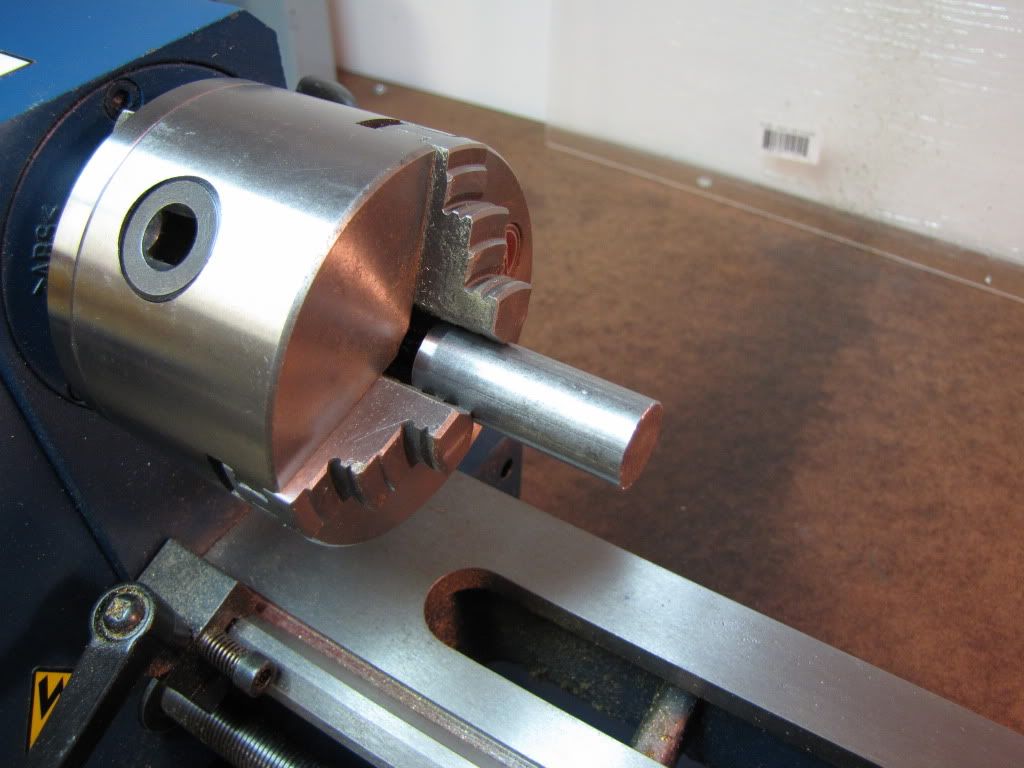
Chucked and ready...

IMG_0182.jpg


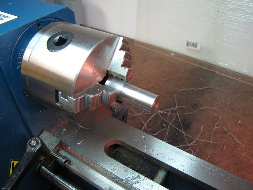
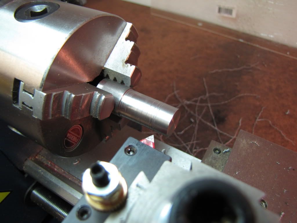
Faced and turned to size. Rats. Two rats. Very carefully snuck up on the size...barely taking anything off...trial fitting the cylinder between cuts. Oops. 1st rat. Slips right on. Hadn't expected that. .005 at a time...why did that round seem to cut so much more off? Was careful to take out backlash...besides...should have been gone at this point anyway. Oh well...nice fit. Maybe I'm lucky. 2nd rat. See that bump about 1/2" in or more? Well don't really care about that...there's a smaller one about 1/4" in. I do care about that.

IMG_0183.jpg


Well if it's bad it's bad. Continue on. Need the practice with the next several steps anyway.

3 grooves. Used my threading tool. It's a very small touch.

IMG_0184.jpg


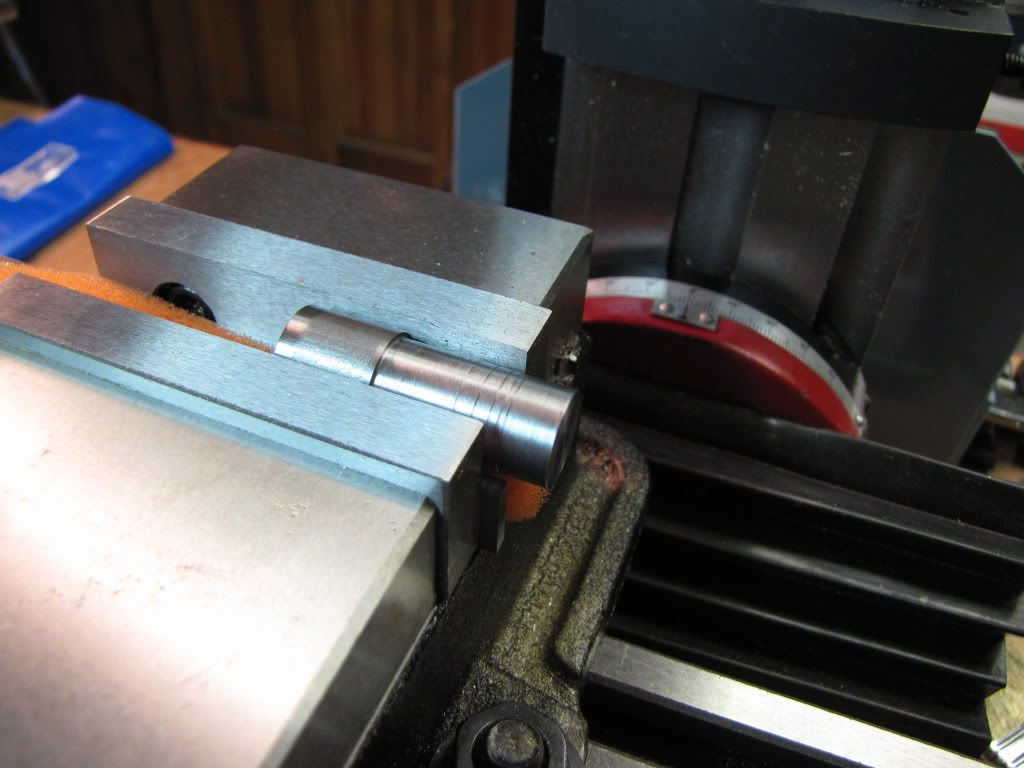
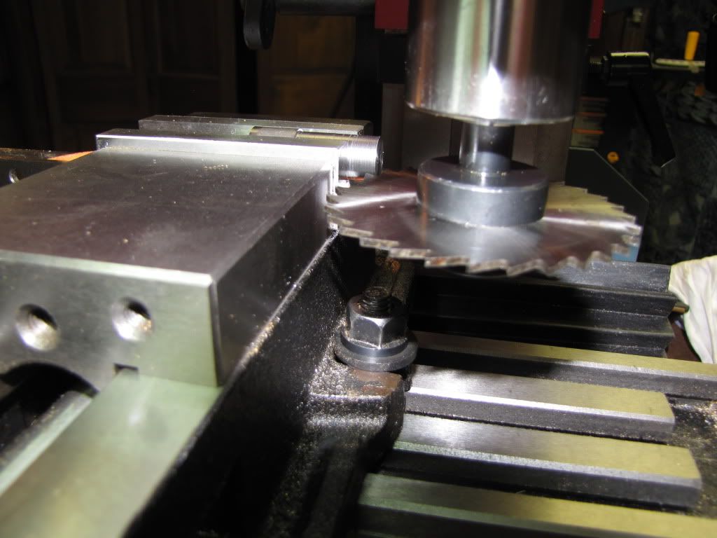
Now for the slitting saw...here's the set up...

IMG_0185.jpg


Now too happy. Seems to be hanging out there. But that's what the instructions say. There's two parallels under the part with my bit of halloween foam in between.

Lined up the slitting saw. Used paper on top of part and brought the saw down. Kept moving the paper until the saw held it. I wasn't about to turn on the saw.

IMG_0187.jpg


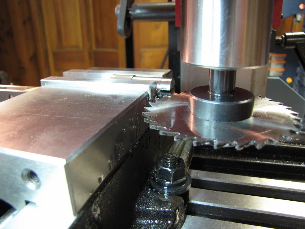
Took small cuts at slow speed (instructions weren't too clear). 1st time using a slitting saw. Very scary. Hey...seems pretty good.

IMG_0188.jpg


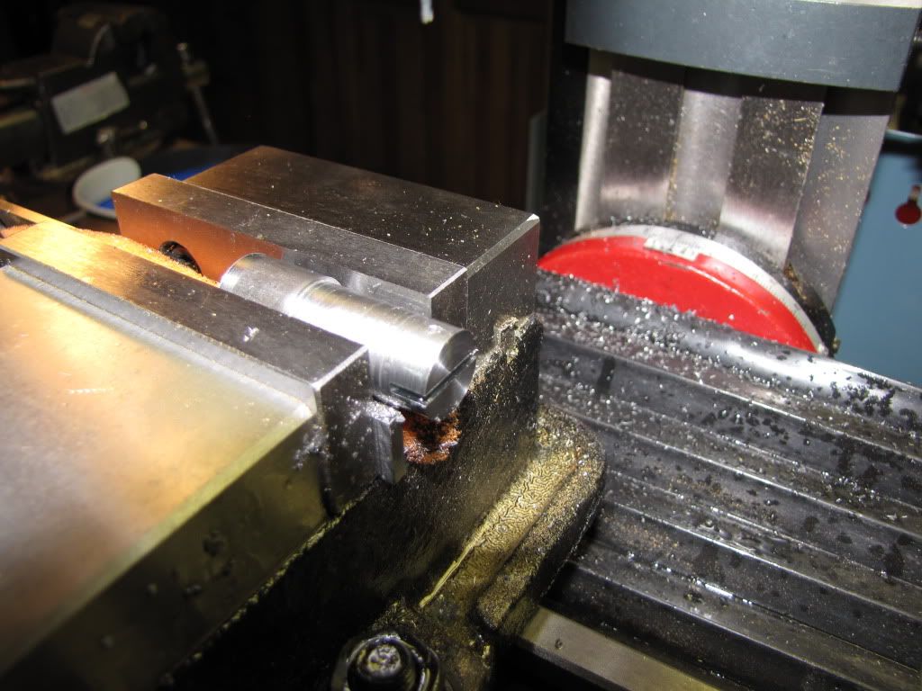
Now to drill/ream the hole for the pin that will hold the connecting rod.

IMG_0190.jpg


Disaster.

Broke the drill bit. It sure didn't take much pressure. Or maybe I don't know what much pressure is.

Done for the evening. I'll start the do-over this weekend.

I could maybe salvage this...drill from the other side far enough into the bad side then cut the pin shorter. Nah. I have no idea how far the broken drill bit went.

Let's see if anyone has ideas on how to remove a drill bit. The material I'm drilling is 1018 CRS.

Can't get too upset when I find an excuse for a vodka martini.
 
Carl,

Sorry to have read about the broken drill bit. What "colorful" words did you use when it happened? I know I probably invented some new ones when that happened to me.

Bob
 
90LX_Notch said:
Sorry to have read about the broken drill bit. What "colorful" words did you use when it happened? I know I probably invented some new ones when that happened to me.
Bob

Hi Bob. Surprisingly...it was just an 'aw rats'. I'd already had the disappointment of a poor turning (that was an 'oh crap'). I was pretty happy to be able to be doing anything tonight. And, I was coming off a 'used a slitting saw for the first time and didn't hurt myself'. Now...had it been my second try....well...that kind of language I'll just keep to myself. No sense destroying the image some people have of me. :big:
Thanks. I hope your new words were 'one shots'.
 
Whenever you can (as in this case) drill first, slit/mill/etc. second. (Klotz's second law of machining). Whether you believe it or not, steel is flexible. You want the drill to see solid material all the way to the bottom of the hole. The saw/mill doesn't care much about cutting air.

Were you using a carbide tool to bring the piston to size? Carbide doesn't like to take fine cuts. It tends to "float" (my terminology - not a recognized machining term) until given a big enough bite at which point it takes the full depth cut. HSS doesn't have this annoying property. Grind a good HSS tool with a reasonable (for the job) radius on the tip and a scary sharp edge. Yes, more tool grinding. I know you don't like it but it's essential to the craft and you need to master it.

Don't try to salvage the part with the broken bit. Steel is cheap and it's not worth the frustration. We'll talk about removing broken drills/taps when you break one in a part in which you've got over forty hours invested. :)

Terminology:

"the pin that will hold the connecting rod" is called a 'wrist pin' or, in UK-speak, a gudgeon.
Actually, in Europe, a gudgeon is a skinny fish frequently used as bait. Maybe our English cousins can explain how the name got associated with engines.
 
mklotz said:
Whenever you can (as in this case) drill first, slit/mill/etc. second.

Were you using a carbide tool to bring the piston to size?

Yes, more tool grinding. I know you don't like it ...

Don't try to salvage the part with the broken bit.

"the pin that will hold the connecting rod" is called a 'wrist pin'...

As a matter of fact...when I read the instructions I had thought to myself that I would rather have drilled first and then sawed. I should've asked the question on the forum first...the people here answer so quickly. Not that it would have made any difference in this case. The bit broke before getting to the slit.

Carbide? Uh..yes but now I'm glad I did. It provided the opportunity to learn that tidbit about float and then taking a chunk. (How do you like that for saying...'sure, I meant to do that'?)

So I came across as not liking to grind tool bits huh? Probably right but I'm sure it's temporary. Right now I want to build and I have the silly notion that I should be able to do a beginner's kit with beginner's skills. (I don't mean to put other newbies off...there are beginners kits and there are beginners kits.) I can see how grinding one's own tools will provide flexibility and satisfaction.

No salvaging.

'wrist pin'. Thank you. I always appreciate that kind of stuff.

Thanks Marv.
 
The (turned-down) piston is being held by the unturned stock at a good distance from the point at which the drill enters. I can't tell from the photo but there doesn't appear to be any support under the piston near the edge of the vise. Mayhaps the part pivoted slightly under the downward force of the drill. Little drills don't like that.

Since you don't have collets and a collet block (tell the Frau you need some for your next anniversary) try using a V-block or similar to grip closer to the point of drilling when you make the next one. Even a V-block on the unturned part would be better than what I see in the pictures. As in the bedroom, rigidity is a virtue in the shop.

Use some lubricant when you drill. Little drills like to get swarf-choked and lube will help it to slide off. Withdraw the drill often and toothbrush it while it's spinning to get the plaque off. (Klotz's second law of machining - never throw a toothbrush away.)
 
mklotz said:
The (turned-down) piston is being held by the unturned stock at a good distance from the point at which the drill enters.

Yes. That bothered me too. Again...I was going by the instructions. This is the nth time that the instructions seem to fly in the face of 'good practice', or at least 'better practice'. But I don't want to be too negative about the kit. When I was starting out...gosh it must be all of four months now!...I had great difficulty finding something I felt I could do. The lesson for me is...seek help. And this forum provides that in abundance.

mklotz said:
As in the bedroom, rigidity is a virtue in the shop.

Yeah..well when you're by yourself...it's a hobby. (She comes home in two months! Boy will I be virtuous!)

mklotz said:
Use some lubricant when you drill.

We're talking machining right? (Well that's just bad. I won't blame a moderator for knocking this out.) Yes...I've used lube every time I drill and ream. But on that note, I came across a reference that indicated it wasn't done for brass. Your thoughts?

I think your remark about swarf has the most merit. I remember thinking at the time...'maybe I should pull up and clear' and then 'snap'. I'm not a fast guy you understand.
 
zeeprogrammer said:
Disaster.

Broke the drill bit. It sure didn't take much pressure. Or maybe I don't know what much pressure is.

Yup, piece may have shifted down a tad from the drill pressure. Vise holding part on the larger diameter, little lever action. Did the bit break just as it reached the saw cut, breaking out of the material and suddenly with less resistance your hand pressure causes the bit to cut more material. What gives first, the material being cut or the bit.

I have broken 1/2 inch bits from not watching when they break through the stock and I know better. When getting near the end of stock kinda "Peck at it" so the bit doesn't try to thread its way along that last little bit.

V-Block, I've seen you have one, as Marv suggested try that as the support for the next one. Don't worry, that wont be the last bit broken :), don't fret over it either, it happens to everyone. My kid busted a new $40.00 3/4 drill bit a while ago "Gee dad I dont know how it happen"

 
Drilling lubricants - my take...

Brass - none needed but "peck" drill on deeper holes. Use the toothbrush.

Cast iron - contains graphite so lubricant not needed. Use the toothbrush.

Aluminum - kerosene keeps it from sticking to the drill/mill/reamer. Use the toothbrush.

Steel - sulfurated cutting oil. Use the toothbrush.

Copper - (whole) milk. Messy but it works. Copper is a royal ***** to machine so avoid using it whenever possible.

Every machinist has his favorite lubricant - everything from lard oil to bacon fat to ATF.
My ideas are only suggestions. Try different stuff and decide what works best for you. There is no "correct" substance. The important thing is to use something (except on brass and maybe CI).

Go to trade shows like EASTEC or WESTEC. Many vendors pass out small samples of their latest snake oil to try. At our usage scale, you'll get a year's supply for free.
 
Fascinating stuff Zee - I admire your attitude and the ability to ask the questions that spring up in my newbie mind!

With regard to Marv's "poser" re UK-speak and "gudgeon"

mklotz said:
Actually, in Europe, a gudgeon is a skinny fish frequently used as bait. Maybe our English cousins can explain how the name got associated with engines.

the following is lifted straight from the Oxford English Dictionary online -

noun 1 a pivot or spindle on which something swings or rotates. 2 the tubular part of a hinge into which the pin fits. 3 a socket at the stern of a boat, into which the rudder is fitted. 4 a pin holding two blocks of stone together.

— ORIGIN Old French goujon, from gouge ‘chisel’.


Regards, A
 
Foozer said:
When getting near the end of stock kinda "Peck at it" so the bit doesn't try to thread its way along that last little bit.

Foozer: Thanks for the tip. I would not have thought the bit would 'thread'.

mklotz said:
Brass - none needed but "peck" drill on deeper holes. Use the toothbrush.
Cast iron - contains graphite so lubricant not needed. Use the toothbrush.
Copper - (whole) milk. Messy but it works. Copper is a royal ***** to machine so avoid using it whenever possible.

Why is it that I understand cast iron and graphite but the idea of brass and no lubricant bothers me?

But that reminds me...when trying to fit the cylinder to the piston I noticed that the cylinder hole had very nice edges on one end but somewhat ragged on the other. I think the ragged edge was the exit for the drill/reamer. The drill/reamer was new...I might have used the drill 2 or 3 times on cast aluminum. I'm thinking it's the brass being pushed out and torn away. Perhaps I fed the drill too fast? Could it have been caused by the reamer?

Whole milk in this house? She'd kill me.


Alasdair: Thanks. And thanks for the definition. I like that stuff. Some of my home reading includes 'the origin of words'.
 

Latest posts

Back
Top