Lots of questions... I've interleaved my answers
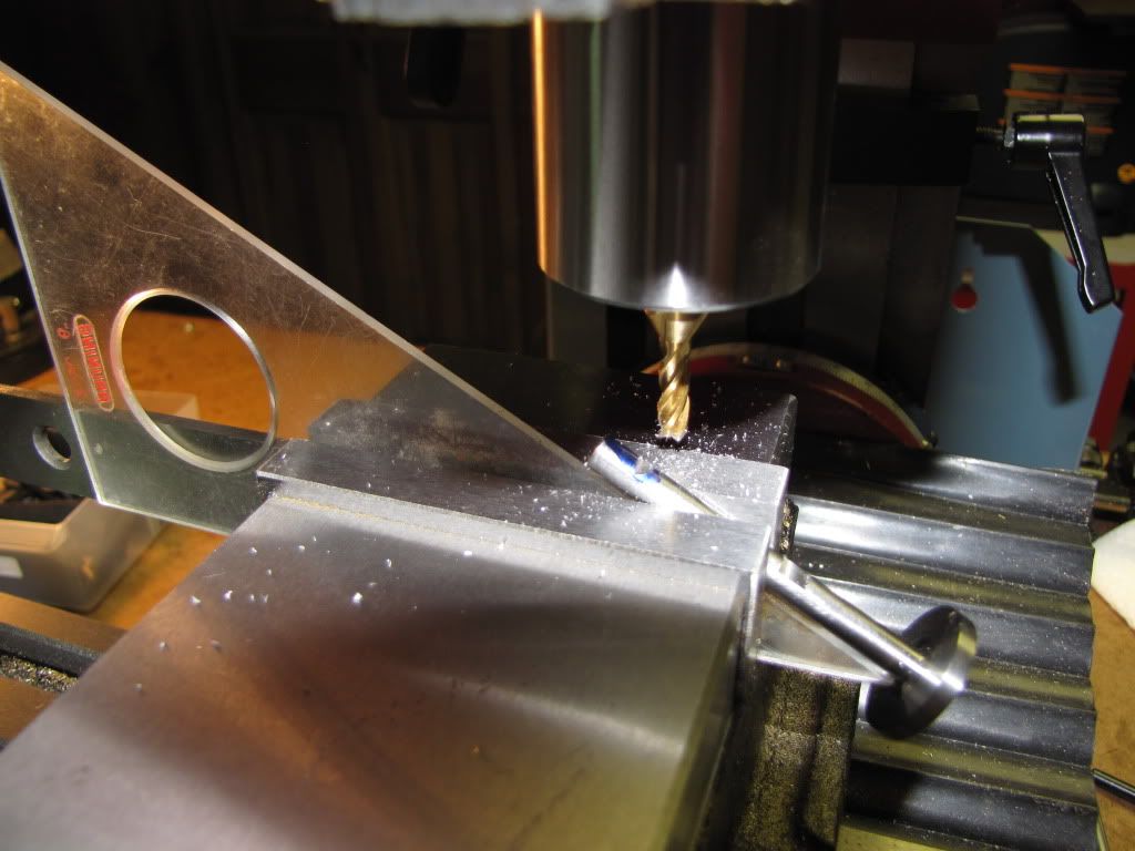
Yes I was bothered about using the triangle. I tightened down pretty good...but still.
***But you're tightening on the crankshaft, not the triangle.
Thanks for the links. Not sure they would work...1/4" thick is thicker than the crankshaft.
***That's what pusher blocks are for. Eventually you'll have a whole box full in every conceivable size. It's what mistakes become when they transmogrify into tools.
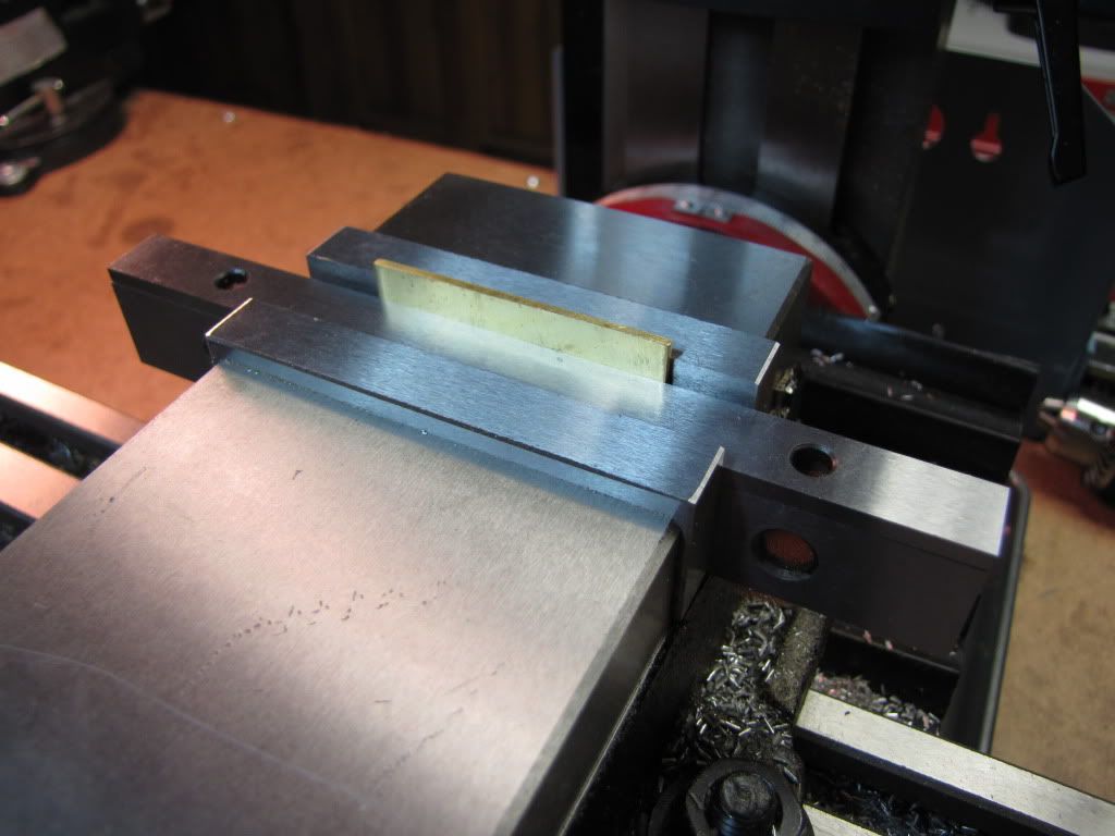
I have a sine bar...but to be honest...I didn't want to move the vice for this one cut. What I should have done is wait until all the other parts are done that needed the vice and then moved it.
***I apologize. My vise is big enough that I can simply drop the (2.5") sine bar into it.
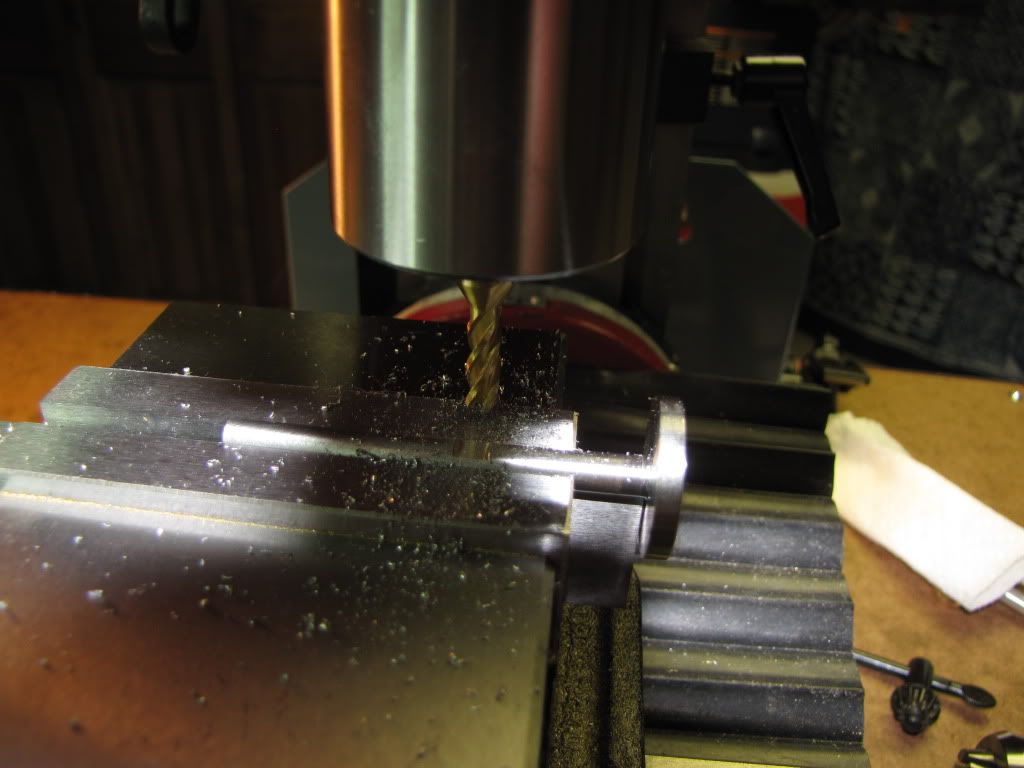
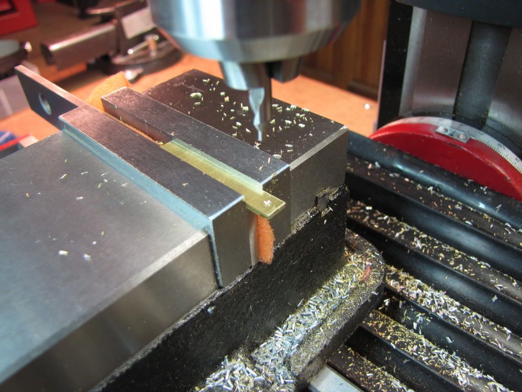
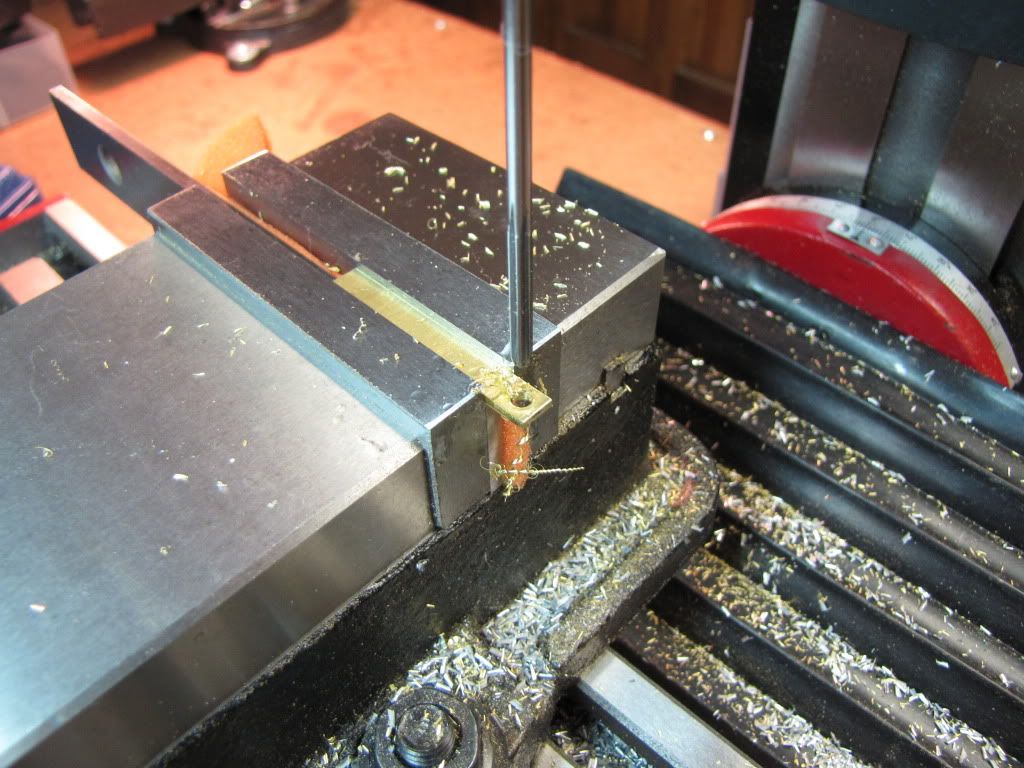
No I hadn't checked the diameter of the pin. Should have. I did drill under 1/64 before reaming.
***Good onya. You're not forgetting what you learned previously.
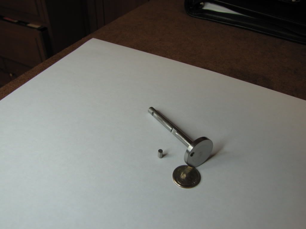
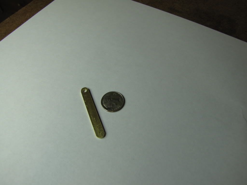
I just measured...the pin is 0.125. the reamer also 0.125. So I don't think it was intended to be a tight fit despite what the instructions said. Looking at the drawing, the hole tolerance is -0.000/+0.002. That also seems to indicate a 'loose' fit or the pin is supposed to be bigger than 0.125.
***Dumb tolerancing if they want a press fit. 0.125 -0.001/+0.000 would have made more sense. It's not that big a deal. Loctite is your (and my) friend. Type 609 is called, IIRC, "press fit assist" and is the best thing since sliced bread.
Would it be better to have reamed at 0.124? I do have a set of over/under and have the 0.124. Could I have pressed the pin in with 0.001? Then, had I measured the pin I would have been good.
***A thousandth is a bit on the large side for 0.125" but, with the assistance of a brass BFH, it would be possible.
I don't know enough about press fits and what tolerances are required. Could temperature have figured in and caused the metal to expand/shrink?
***A good tool for novices trying to deal with all the possible types of fits is my program, surprisingly named FITS. It isn't as thorough as MH but it works well for our less demanding work and is infinitely easier to use.
I haven't measured the hole...don't really know how I'd get an accurate measurement.
***Holes that small are usually measured with pin gages.
http://www.use-enco.com/CGI/INSRIT?PARTPG=INSRAR2&PMAKA=616-8126&PMPXNO=950065
This is a specialized tool and you'll be happy to hear that you don't need to buy it yet. I'm simply showing you what I'm talking about with the URL.
On that note, I'm not a salesman for ENCO. It's just convenient to use their (or MSC's) on-line catalogue to dredge up a picture to show you what I'm talking about. No endorsement of the product shown is implied or intended.