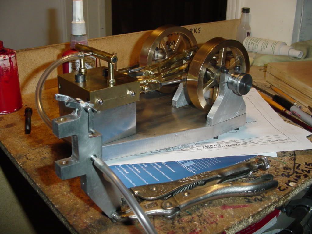
I'm new around here and have just gotten around to following this thread. Really neat project. It will really add something to the appearance of that engine.
Just wandering if anyone has given any thought to the failure modes and the consequences of failure. At the speeds and loads involved here I'm sure there is no danger, I'm just thinking. How does it go in full scale steam engines driving a load, what happens?
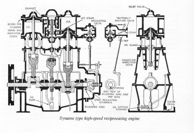
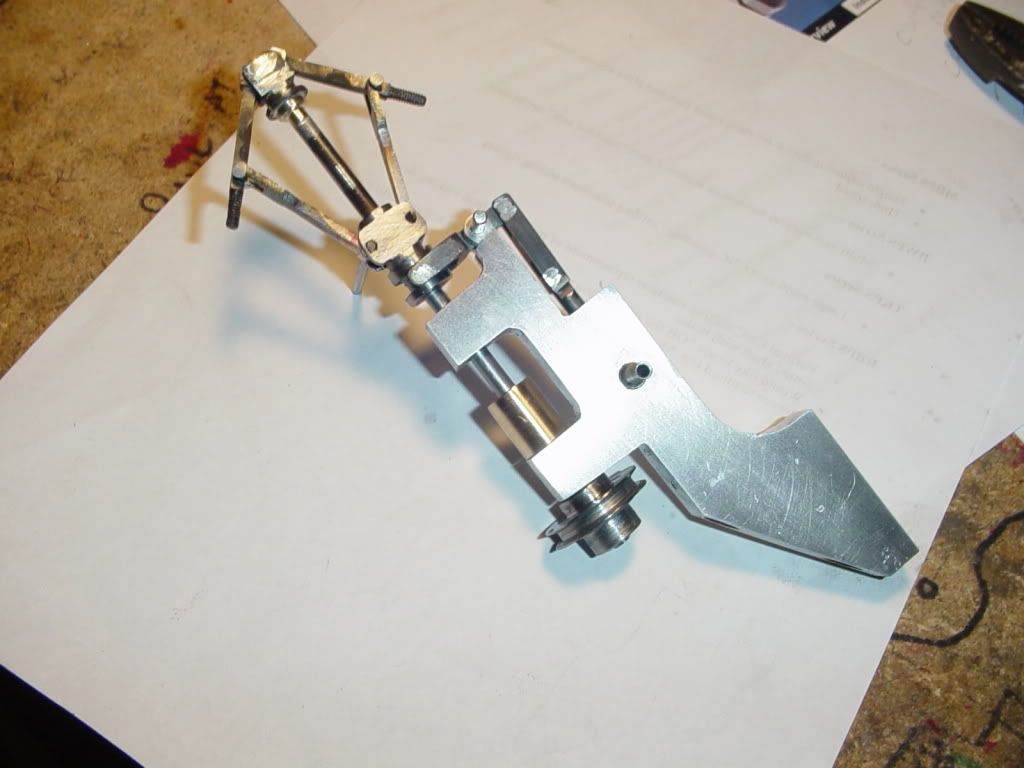
1. If the upper pivot pin fails the spring drives the collar to the bottom and the valve is wide open - overspeed.
2 If the middle pivot pin fails, same as above.
3. If the lower pivot pin fails, same as above.
4. If the collar escapes the control fork, I'm not sure which way the valve would go.
5. If the drive belt parts or jumps the groove, rotation halts, the balls fall and the throttle goes wide open.
Other failure modes, say the loss of a weight or bushing failure or failure of any part of the linkage the the consequences would vary. What happens? I have no real world experience but it seems like it would be a good idea to design some linkage with a "fail safe" limit that would close the valve and become locked out until reset if the engine exceeds a safe speed. I'm thinking of this as some kind of mechanical intelligence that is getting its signals crossed. It is seeing a need to open the throttle when it should be doing the exact opposite.
Is this a problem in the real world of steam power?
Jerry


") ...... great progress ......... I have trouble keeping up with your posts, never mind the machining .... keep up the good work feller :bow:
...... great progress ......... I have trouble keeping up with your posts, never mind the machining .... keep up the good work feller :bow: