Newest project--A Flyball Governor

Home Model Engine Machinist Forum

Help Support Home Model Engine Machinist Forum:

This site may earn a commission from merchant affiliate links, including eBay, Amazon, and others.

Brian, You want something to put a variable load on your engine so the new governor does it's job?

How about a shredder for ping-pong balls, fun to show off with, or
a nut cracker, build up stress and then relieve it, or
a geared down water pump, more force required on lifting stroke than on return, or
such?

earl...
 
potman said:
Brian, You want something to put a variable load on your engine so the new governor does it's job?

How about a shredder for ping-pong balls, fun to show off with, or
a nut cracker, build up stress and then relieve it, or
a geared down water pump, more force required on lifting stroke than on return, or
such?

earl...

Earl---I've been way to busy to give this much thought. Whats perking in the back of my mind is something similar to the slinky machine, but with two different loads, one heavy and one light on the pads that the slinky attaches to---


My vote goes to the nut cracker!
 
I am quite pleasantly surprised at just how responsive this governor really is, and how well it does control the speed of the engine. It does operate just as I had anticipated. On the initial rush of air when I turn on the main air supply valve, the engine self starts, begins to revolve, and very rapidly begins to ramp up to what could be a run away engine. The governor balls rotate faster and faster untill centrifugal force begins to move them into a "balls out" condition, and the valve in the governor begins to close and choke off the incoming air. It stabilizes very quickly, with the ball position and the speed of the engine become constant, with no visible oscillating. I know that the governor is controlling the engine speed, because if I override the position of the valve, the engine begins to rotate much faster, then if I let go of the valve, it settles back into its constant speed. When I impose a load on the engine (at high air pressure, around 60 PSI) by holding my thumb against the rim of flywheel, the engine begins to slow down, the valve opens, and the engine picks up speed again, even with the load imposed, trying to hold that constant RPM. I hooked it up to the slinky machine (which really requires very little torque to move it). By sliding the engine on top of the table untill the o-ring belt went slack and the slinky machine was not working, then pulling the engine back untill the belt tightened up and the slinky machine began to work, I can actually see the lever working to open the inlet valve wider and hold the constant speed. There has to be some change in the engine RPM to initiate movement of the balls, so as soon as the load comes on, the engine dies just a little. Then as soon as they move the engine begins to get more air and the RPM picks up to where it was previously. I have discovered that it doesn't respond all that well to rapid changes in the load, but when the changes are slower it responds very effectively.
 
Well I think it's a load of Balls ;D ............. never thought I'd get away with saying that on a family forum ::)

Brian .......... I've been watching this thread with interest and, as usual, it has rocketed along ........... from conception, through design, manufacture, completion, commissioning and having a running model in very short time ......... congratulations are in order :bow:

First class sir 8)

CC
 
I just posted a complete set of engineering drawings for this governor in the uploads section, in .pdf format. You are welcome to use them--if you download them I would appreciate a karma point. Its a fun project.---Brian
 
Brian,

Thank you for a wonderful thread!
applause.gif
You have a remarkable talent for taking a concept, running with it, and bringing it to fruition. I am humbled.

Is anyone else here amazed at what the internet has done as far as being able to share our work with others -- in "real time"?

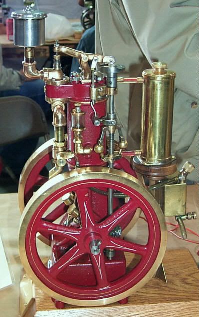
And on the subject of flyball governors, it's worth noting that these were sometimes used on IC engines as well. Not long ago, Shelf Pet Models came out with a highly interesting 1/3 scale model of a the 2-1/2 horsepower Red Devil hit/miss engine. It uses a flyball governor on a gear-driven vertical sideshaft:

REDEVIL8.jpg


An absolutely beautiful engine, in my estimation, but alas at the very outer limit of my machine capacity, if not exceeding it. :-\

Once again, Brian, thanks for sharing your project with us.

Paula
 
I have decided that I would like to slow the optimum speed of the engine down a little. I tried clipping a bit off the end of the compression spring, and although this did slow it down a little, it did act as if it might want to oscillate when the spring got weaker from shortening it. I then tried to buy some 5/8" brass balls from McMaster-Carr, and was informed that they no longer ship to new customers in Canada. Chuck Foster, (a neighbour in Ontario) who GAVE me the first two 1/2" diameter brass balls for the governor has informed me of a fellow on Ebay who sells to Canada. He goes by the name "Toolsupply" on Ebay and his email address is "[email protected]" . i just went on Ebay and put "brass balls" into the search engine and very quickly found him. His prices are reasonable, and he does accept Paypal and ships to Canada.---Brian
 
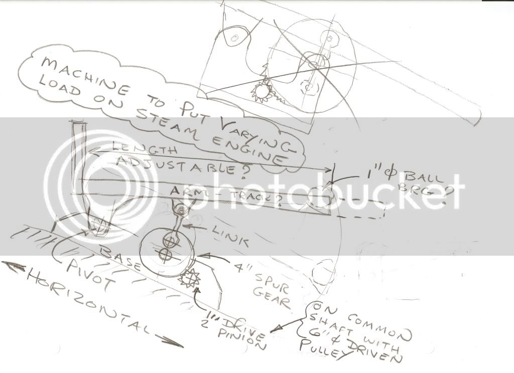
I have done a rough sketch of a machine which would apply cyclical varying loads to the steam engine to make the governor work. The load applied would vary over a fairly long time period because of the gear reduction, first from the engine pulley to the driven pulley, then because of the gear reduction at the machine itself. As the cantilevered end of the track slowly lifted up , that would be the load side of the cycle. When it began to descend, that would be the non load side of the cycle. The bearing, which would roll back and forth, is just eye candy.--It doesn't actually have to be there for the machine to apply a varying, cyclical load.
scan0001-1.jpg

 
Brian

I followed Kevin's thread that leads to Google Books and was paging through the handbook re Corlis engines and spotted some interesting text. On page 16 of that book, the following quote:
"We should also see that the oil, or dash pot, is in good working order, with a constant supply of oil to gently retard any sudden fluctuation in the movement of the regulator"

The following page shows a governor with the dash pot labeled as "Water Pot".

A dash pot might make an interesting project and help with the governor fluctuation. Check it out.

http://books.google.com/books?id=xL...building&lr=&as_brr=1&as_pt=ALLTYPES#PPA16,M1

Jerry
 
Let me try making a link

http://books.google.com/books?id=Gb...tomatic&lr=&as_brr=1&as_pt=ALLTYPES#PPA344,M1

This actually starts as math, and I would seriously have to sit down with some books and some paper for about a week to get everything he's postulating with them thar numbers. But by the middle of page 345 he gets to the meat and potatoes he was cooking up.

Best translation I have. The rotational motion of the balls is inherently unstable with a tendency to destructive excesses. But with the addition of a spring(my interpretation) that closely matches(reacts to) the FORCES created by the momentum of the spinning MASS the whole whirlygig is returned to Ballarina like balance and perfection(my embellishments as well :p)

I assume from the shape of his equations the action of the spring will be very NON linear.

Anyone ever make a spring (or found something) that has a non linear response? I know in electronics we use linear taper and log taper potentiometers based on the control response needed.


I'm new so I don't know if this helps the group of people here or not. (Still lots of juicy tidbits in the book though) ;D


Goodnight to the bookworms,
Kermit
 
Kermit

I'm not much on electronics, but don't you use something like resistors to dampen voltage oscillation. That's what a dash pot does. It dampens the oscillation of a spring or other physical input.

Jerry
 
Thanks Jerry

That "Dash Pot" is gonna be the object of inquest for me today. Actually it was the word pot that got me thinking electronics, because pot is our shorthand for a potentiometer, also called a variable resistor. I'll probably feel silly about my comment once I learn more.

Always putting the mouth in gear without starting up the brain,
Kermit
 
You may want to search on "dashpot"-- I usually see them without the space and it will cut down the smokeable unrelated hits considerably.
 
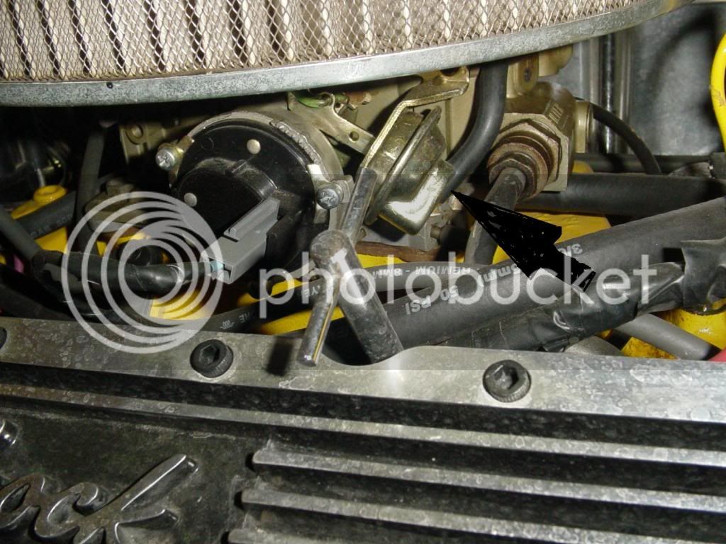
A mechanical "dashpot" is generally an enclosed cannister with a membrane closing off one side of the cannister from the other. A mechanical "piston rod" when pushed on from outside the cannister causes the membrane (diaphragm) to flex, and pressurize air on the other side of the cannister. There is a very small air release hole in the side of the cannister, on the side opposite from the push rod, called a "controlled orifice"----It lets the air out slowly. So--basically, its a kind of shock absorber, which is used to make a mechanical linkage move slowly during the last bit of its travel. Back when the earth was young, and cars still had carburetors on them, you always would see a dashpot on the throttle plate mechanism, to prevent the engine from slowing down too rapidly and consequently stalling when you slowed down from a higher speed.---Brian
 
basically an inertial damper then! allows full range of motion but slows the reactions of the governor down?


Latest posts

Back
Top