My next build--A cross beam vacuum engine

Home Model Engine Machinist Forum

Help Support Home Model Engine Machinist Forum:

This site may earn a commission from merchant affiliate links, including eBay, Amazon, and others.
The cam needs to be quite a different shape to the usual IC engine profile to get that quick open and close together with dwell. Also depends if the "high" part of the cam is closing or opening the shutter
 
Alternatively, a long stroke valve, with a slot that passes the inlet port, and continues to slide staying OPEN past the port as the eccentric goes over that part of the stroke until it returns to close the port.
Is that simple enough?
K2
 
Sid, sounds like a cam action is more appropriate han a circular eccentric?
Jason, your slotted lever is almost exactly like mine for the water feed pump on my boat! Great Minds...? n all that? - Or just some understanding of geometry...
K2
Yes, exactly.
You want to get all the flame you can in the cylinder, then the port needs to shut off and seal for the hot air to meet the cooler cylinder, form a vacuum and have atmospheric pressure push the piston back up, then the valve snaps open again to start the cycle over.

Sid
 
I began laying out the flame sucker sideplate this morning. The two aluminum sideplates are Loctited together then epoxied to the plywood backing plate. This layout shows all of the hole centers and external cuts but not any of the internal cut-outs. This afternoon I will lay out the internal cut outs.
LOMpxn.jpg
 
Probably don't want to cut the plywood away as it provides a location for all the various arcs that form the shape. Locate the ctr of each arc on the rotary table and mill the whole shape without touching a bandsaw.
 
This morning I machined the engine sideplates. If you are wondering why that one internal rib is so much thinner than the other one---Just as I was machining that feature, there was a huge meteor strike just outside my machine shop window. The impact was so great it threw my milling machine off axis, and I didn't realize until the part was finished that had happened. I have to go now and move my lawn ornaments to higher ground before the tsunami gets here.
adHi5Y.jpg
 
Steamchick--the plywood was there just to provide a center for my compass to make some of the large arcs. You really can't depend on Loctite or epoxy to hold the parts on the plywood while you are machining them. After the laying out was done, the parts were broken loose from the plywood and held in my machinist's vice for machining.
 
Thanks Brian. - If the meteorite landed on your garden, then it becomes your property.... sell it on ebay! It may be full of valuable minerals? (Ha! Ha!).
I understand your worries about Tsunamis.... they happen all the time in Ontario... - or so I am told? (Never believe all you read on the web! - Sometimes it is true!).
🤣
 
No meteors today. It's 3:11 now, and I've worked since about 10:00 this morning. The base plate and the plate which holds the cylinder in place are finished. The spreader bars are finished, and the ball bearing housings are finished. I could go ahead and make the cylinder today, but right now I've got to go and grab something to eat. I didn't realize how dirty everything on the engine was until after I took the picture.
tJ8ALe.jpg

Yr1ACi.jpg
 
Every time I build a set of flywheels, I seem to come up with a different design. Easiest way is to make a one piece flywheel from a piece of steel, but then there is the question, do I make fancy triangular windows on my rotary table (hard) or do I just drill a series of round holes in the web. (easy but boring). I've made a few flywheels with an outer rim of steel and the web and hub made of aluminum.--Again, this is easy, but an aluminum hub gets chewed up pretty fast if you have to remove the flywheel a few times and then reinstall it during the build. This time I'm going to try something a bit different---I wouldn't recommend this design for a gasoline engine, but for a flame sucker (which at it's very best is a rather wimpy engine) I think this would work fine.
WVPOI3.jpg
 
First step will be to turn a 3" diameter piece of round stock as shown. This will keep the outside diameter of the flywheel rim and hub perfectly concentric and aligned to prevent "wobble.
buqzmX.jpg
 
Next step will be to cut all of the spokes a bit longer than they need to be, coat them with Loctite, and assemble them as shown. Be sure and wipe any Loctite off the spokes where they show, as it is difficult to get off after it dries.--An advantage here is that the spokes can be made of brass for extra "bling".
2qidtY.jpg
 
And of course, after the Loctite has dried for 24 hours, turn the outer diameter again to clean up the end of the spokes, run a reamer thru the bore in case any of the spokes have ran thru into the bore, and then part the finished flywheel off.
PplHt3.jpg
 
I like the method!
A couple of ideas?
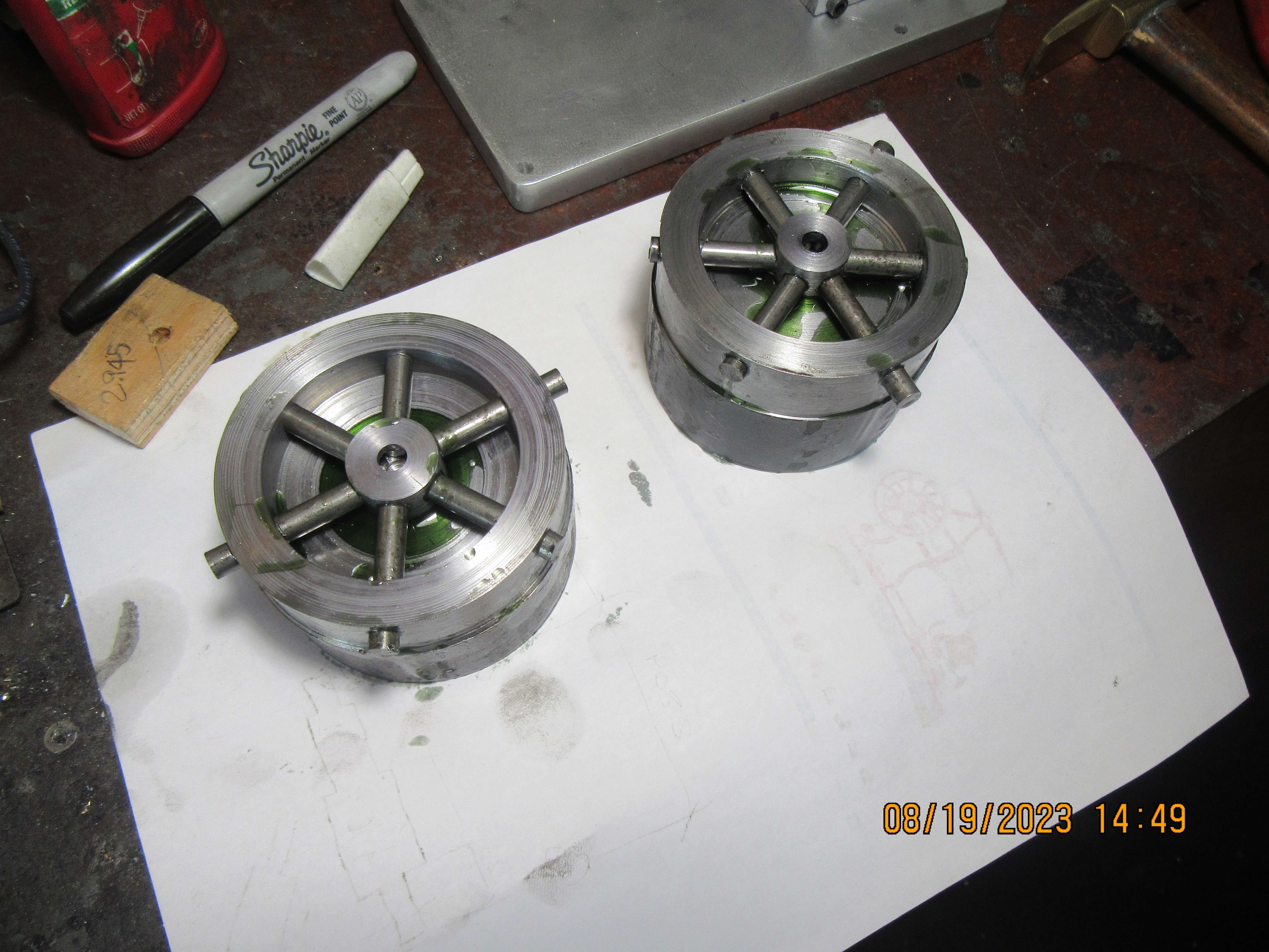
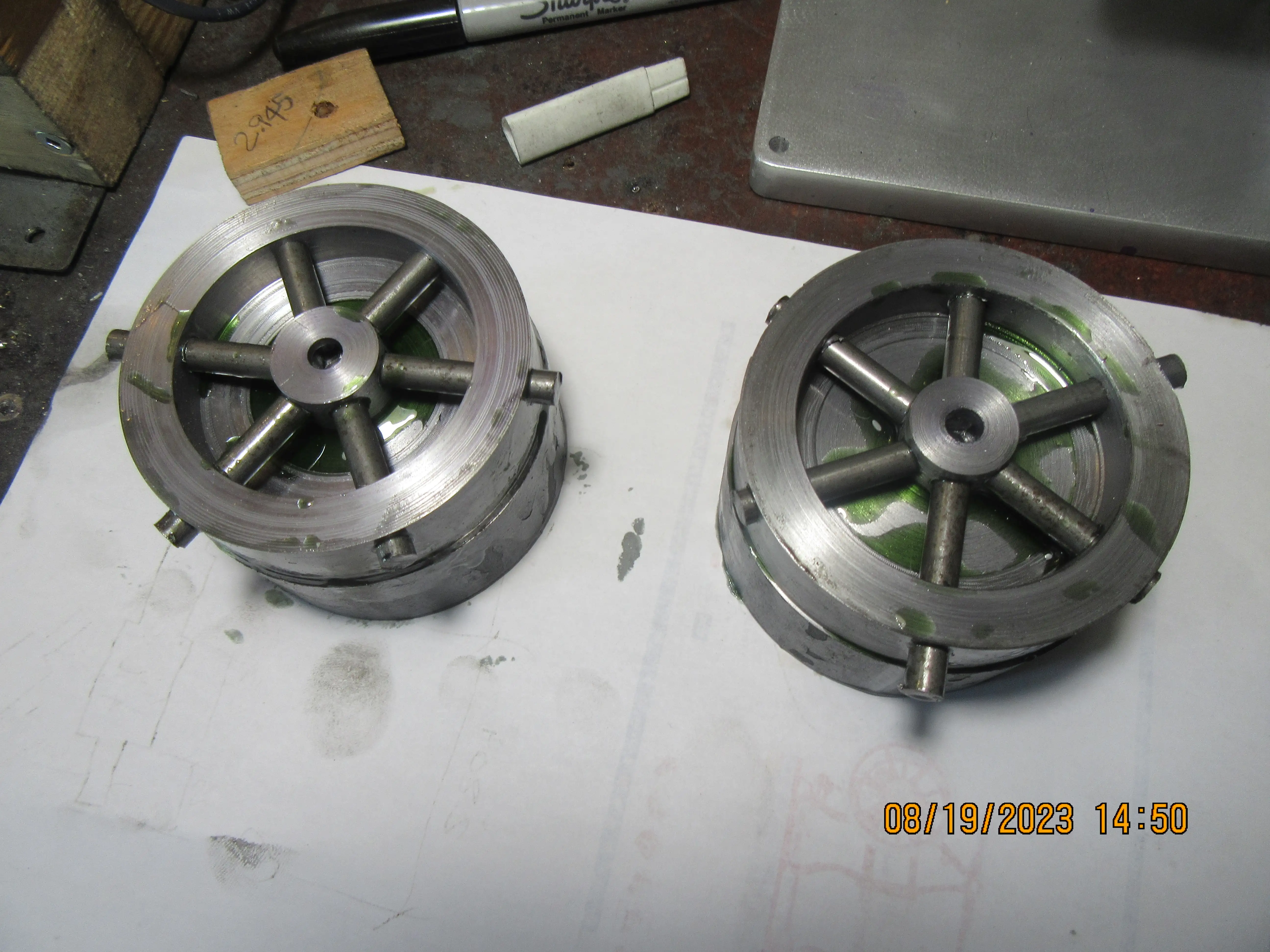
1:insert a piece of axle -well greased - before adding loctite and spokes. Then the axle won't get stuck with loctite, and spokes won't need reaming?
2: tap the hub for threaded spokes... with clearance (spoke OD) in the rim for securing with loctite.
3: leave the spokes 1/8" shy of the rim OD, then insert some steel caps - held with loctite (?) - then when you skim the rim, the outside looks all steel, so observers wonder "how did you do that?"
Or the steel caps could be made with little suds to screw into holes in the ends of the spokes....
Or....

You stimulate my imagination, but I like your ideas Brian!
K2
 

Latest posts

Back
Top